Switch Theme:

[Blind them with SCIENCE] LEDs, Crisis Suits, and You by Big Boss Fearless  [RSS] Share on facebook Share on Twitter Submit to Reddit
»
Author Message
Advert


Forum adverts like this one are shown to any user who is not logged in. Join us by filling out a tiny 3 field form and you will get your own, free, dakka user account which gives a good range of benefits to you:
  • No adverts like this in the forums anymore.
  • Times and dates in your local timezone.
  • Full tracking of what you have read so you can skip to your first unread post, easily see what has changed since you last logged in, and easily see what is new at a glance.
  • Email notifications for threads you want to watch closely.
  • Being a part of the oldest wargaming community on the net.
If you are already a member then feel free to login now.


Made in sa
Bane Lord Tartar Sauce


Saudi Arabia

This message goes out to all the ambitious homeboys, homegirls, and homedawgs who have more gumption than common sense, and who want to take on the challenge of lighting their models with LEDs. This is my first dedicated tutorial, so bear with me as I hammer out the details and fish through my photobucket account for all my WIP pics. This tutorial was originally posted on Advanced Tau Tactica, but I was, frankly, disgusted by the anti-fun nature of some of their moderators (not all, just a couple who desperately need to get laid) and decided to abandon that site. This article will focus on adding lights to Tau units. Why Tau? Well, you can already find plenty of instructional articles on working with Imperial vehicles, and those are all boxy and hollow anyway, making them 'easy mode.' Have you ever tried to mod Tau stuff? It aint easy. Also, I wrote this article during the process of building a Dubstep Tau army (link in my sig).

Why am I writing this article? Surely there are tutorials out there! Yes, there are and I used a couple of them to get my foot in the door, so to speak. One is by the mighty and illustrious Bob Hunk, and the second is a Youtube series by a guy calling himself Devinsdad. The Devinsdad series focuses on using reed switches, which are aggravating in the extreme, and results in a rather clean, but difficult to repair or modify result. The Bob Hunk tutorial is only half finished, but otherwise very solid. My only complaint is that Bob Hunk has a bit of an engineer’s mentality and insists on putting a ton of math and formulae and equations out there that, to those of us who are disinclined toward mathematics, make less sense than Lady Gaga’s wardrobe. So, this guide will serve not as a technical guide, but as a practical how-to from a guy who is only interested in how to make things work, and not the ethereal concepts of how they work. And no bacon dresses, either.

PART 1: ALL OUT OF BUBBLEGUM


SECTION 1
PARTS, SUPPLIES AND WHY YOU NEED THEM


Don’t just skim over this section. There is some really helpful stuff in the breakdown about how to work with each component.

First of all, you’ll need the following:

Enamel Coated Electromagnet Wire
LEDs
Coin Cells
Coin Cell Holders
Soldering Iron
Solder
Green Stuff
Hobby Knife
Pin Vise
Drill Bits
Spare Bases
Wire Cutters
Soldering Armature

And then these are nice to have, but aren’t strictly necessary:

Heat Shrink Tubing
Hot Glue Gun
Glue Sticks
Gel Super Glue
Epoxy Putty (plumber’s putty)
Fiber Optic Wire


Wow! That’s quite a shopping list, but don’t be intimidated. Most of the individual pieces are quite inexpensive, and you don’t necessarily have to get it all in one trip. Let’s go down the list of necessary components and talk a little bit about them. One thing that applies to every single component is that you should always buy spares, because you’re likely to fail horribly on your first couple attempts.

LEDs: Obviously very important. You’re going to want either 1.5mm or 3mm LEDs for 40k models. Anything larger is going to be too big. Check to make sure they require a 3V power supply when you’re ordering them. My advice is to buy a variety pack so that you have lots of options to work with. Order these from any model train supply store on Ebay.

Coin Cells: Often called watch batteries or disc batteries. They come in a variety of sizes, the most common I’ve found being 20mm. Make sure to double check that the ones you get supply 3V of power. Sold at supermarkets and Radio Shacks everywhere.

Coin Cell Holder: These come in a variety of sizes and basically just take power from the battery to a couple of metal leads. You can NOT solder wires directly onto a battery, so you need this kind of a component. This also allows the battery to be inserted or removed easily for when you’re not playing. A good component is the Keystone 106 or 103 coin cell holder. The 106 is slightly better, but the 103 will work if it’s all you can find. You can cut a lot of the plastic nubs and spacers off of this thing to allow it to fit into the model’s base easier, just be sure you keep a few spares handy since you’ll likely ruin the first few. Either find a supplier you can order these from, or buy them on Ebay or Amazon

Enamel Coated Electromagnet Wire: This is a type of wire that uses a thin layer of enamel on the wire instead of a rubber coating. That means that the wire is much thinner and can be used in much, much smaller applications. I use 30 gauge, which is incredibly thin, like human hair almost. When you go to work with this stuff, be sure to scrape all the enamel off of the ends of the wires with your hobby knife so that you can get a good contact. When you’re working with the wires, a good idea is to twist two pieces together. That will give them a bit of rigidity and make them much easier to work with. You probably have to order this off of Ebay or Amazon.

Soldering Iron: Not an expensive piece. I recommend getting a weak soldering iron with only a 25W heating element. It won’t ever get freakishly nuclear hot and become a hazard. Try to find one with a fairly precise tip if possible. They sell these at Walmart or any given hardware store. If you look, you can even find a battery powered soldering iron. Get one of those if you can. The nice thing about those is that, while they'll eat up AA batteries over time, there's no cord. That means you can't accidentally leave it plugged in and burn your house down, and also when you're working with a delicate bit of wiring, you won't have the heavy cord getting in your way. Much easier to use.

Solder: No need to get anything fancy. The cheap stuff will do fine. Sold at Walmart or hardware stores. If you want to make your job a lot easier, look for solder that says "Flux Core" or "Rosin Core." That kind will have a chemical called Flux built in, and it does some complicated chemistry nonsense that I can't be bothered to learn the theory behind. The important thing is that it makes the solder stick to the wire you're soldering and not the soldering iron. For a beginner, that is SO HELPFUL!

Green Stuff: Always useful, especially when you’re going to be chopping up bits. Use this to repair your models after you’ve carved them up.

Hobby Knife: Get some spare blades and maybe a spare knife. You’ll be hollowing out parts and drilling into things, which tends to wear out the blades or snap them entirely.

Pin Vise and Drill Bits: Always useful for modeling. However, you’ll be using this now to drill through entire bits, up legs, into arms, et cetera, to hollow them out and make a channel for the wires and LEDs. Go to your local hardware store and pick up a couple each of .5mm, 1mm, 1.5mm, and 2mm drill bits. Avoid any and all temptation to use a powered drill. I’m going to say that again for those of you who are either just skimming or are totally overconfident.

DO NOT USE A POWERED DRILL

Did you get that? Good. It’s a pain in the neck and time consuming to do this by hand, but any use of a power drill is just going to destroy your models irreparably. Trust me on this. Load the drill bits into your Pin Vise (you may need to flip the chuck or change it out with a spare one, many vises come with different chucks in the handle) and start with the thinner bits, then slowly open the hole up with larger bits.

Wire Cutters: Your sprue clippers will work fine for this because the wires are so fine. If you want to get dedicated snips, go for it.

Spare Bases: You will screw this up. Badly. Many times in a row. Until you get the hang of it, then it’s easy. Until then, you’re going to want to get a pack of extra bases. Now, the 20mm Coin Cell Holders are too big to go in the standard 25mm GW bases (there’s an extra part that sticks out to the side). You have a couple options for 25mm based infantry. Either scale them up to a 40mm base, or instead use the 30mm rounded lip bases from Warmachine or Dark Age, Malifaux, or any number of other systems. They look nice anyway. Personally, I already had models on regular GW bases before I started putting LEDs in so I stuck with them. You’re probably looking at putting LEDs in battlesuits, so start by getting extra 40mm bases.

Soldering Armature: This is optional, if I’m being honest. But I’m not. I’m lying right now, so get yourself one of these. You could probably find a way to solder without it, but don’t. Just don’t. You’ll burn your eyebrows off and never see the cat again. These things cost maybe 15 bucks on Amazon. No need to be fancy about it. They come with a couple of small, articulated clamps so that you now have 4 hands. I cannot stress how easy this makes the project. Also, it looks really cool sitting on your desk holding disassembled battlesuits, and I've taken to calling mine the "engineering bay." Don't judge me.


Okay! That’s it for the absolutely essential components. Now, there are a few things that are really helpful to have.


Heat Shrink Tubing: Rubber sleeves that shrink when you apply heat, these are useful for coating a length of wire to prevent shorts, or securing an LED right up against the end of a fiber optic wire. You can use a lighter, a heat gun, or you can just use the soldering iron you already have. That’s how I do it.

Hot Glue Gun and glue sticks: The thick globs of glue this puts out are really helpful for securing the battery holder in the base. Also, you can glob the glue over exposed wires to prevent them from touching and shorting out, since the glue is an insulator. Very handy to have!

Gel Super Glue: What’s wrong with the regular kind? Well, it’s liquid. Liquid runs. If you’ve hollowed out a model’s leg and run a wire through it, then when you glue that leg back together the glue will run down that tube and stick the wire to the inside of the leg. And there is no getting it loose. Trust me, you want some slack on your wires. Gel glue makes things a bit easier, and can also be used like the hot glue to insulate a wire.

Epoxy Putty (plumber’s putty): A cheap 2-part epoxy, very similar to green stuff only it dries more rigidly and much faster. You’ve got maybe 4 minutes of work time. The value of it is that you get a lot of it for very little money, which means that you can use it to cover up an entire base with a basic sort of terrain. Works very well for covering up your battery holders in your bases.

Fiber Optic Wire: This one is difficult. I don’t mean a finished fiber optic cable, but the individual fibers. I would search for Plastruct FOP 30 and FOP 10 for exact product names (.3 inches and .1 inches, respectively). This fiber gathers light in one end and transports it to the other end, losing almost nothing along the way. That said, it is incredibly frustrating to use. Don’t try to bend the FOP 30, because it doesn’t like to bend. But you can run it down the length of an arm and out the barrel of a gun, or through the eyes of a model to adjust a glow effect, as I’ll show you later in the tutorial. One important thing to note is that this material expands when you add heat. This means that if you touch your soldering iron to the tip of a wire, it will mushroom outward. This is useful for a number of reasons I’ll go into later.


SECTION 2
CREATING A POWERED BASE


For this, you will need the following:

Coin Cell
Coin Cell Holder
40mm base
Hobby Knife
Green Stuff –OR- Hot Glue Gun

1. Place the battery holder on the base and make a mental note of its proportions. Try to keep it over to one side rather than sticking it square in the middle.
2. Drill down into the base with your hobby knife and start widening the hole, carving a large circle into the base.
3. Constantly check and re-check your hole in comparison to the battery holder. You only want it to be a little bit bigger than the holder.
4. Put the battery in the holder. Do not skip this step or you are screwed later.
5. Is the battery in the holder? Put it in there. The holder has a clip that keeps the battery in place. Inserting the battery slightly increases the holder’s dimensions. If you fit the holder into the base while it’s empty you will have Wobbly Model Syndrome when you put the battery in. So stick it in now, before you forget.
6. Plug in your glue gun and let it warm up.
7. Take your glue gun and quickly put a line of glue around the circumference of the hole you drilled.
8. Quickly grab your battery holder and shove it into the hole. Try to face the open end of the battery holder towards an open space so that you can get to the battery.

9. Before the glue cools, lay the base on a flat hard surface like a desk top, and push downward on the base (not the holder) so that the battery holder rises up and does not cause wobbly model syndrome. If you have the time, try to angle the battery slightly downward so that you can get to the battery easier, but make sure it sits level.
10. Once the glue cools, apply green stuff as a gap filler. Alternatively, you can line the outside of the battery holder with green stuff and use that as an adhesive. Either way works.

How easy was that? Creating a workable base is probably the easiest step of this whole process. Now, you’ll obviously have to cover that battery holder up, but you have to wait till your wires are attached, much later. For now, just try to come up with a plan for how you’ll do it. I tend to use epoxy putty to just cover the whole base, then bricks and rubble over that as I go for an urban rubble scape. Another method is to place a bit of a structure over it or the hull of a destroyed vehicle. Anything goes as long as it looks good.


SECTION 3
HOW TO SOLDER LEDS


You will need:

Soldering Iron
Solder
Wires
Soldering Armature
Hobby Knife
Clippers

Step One: Watch a bunch of Youtube tutorials. I’m not kidding. There are thousands, and seeing it in a video format will teach you the basics much better than I can. Go on, watch some. I’ll just wait right here.


Did you do that part or are you just skipping? Go back and do it right.


So now you know how to solder. But wait, aren’t most of the tutorials about how to solder a PC board? Yep. That’s where my two cents come in. You see, I’m a moron. I mean that. I am freaking epically slowed. It’s horrible. I licked my soldering iron once, that’s how dumb I am. I managed to stab myself in the junk with my hobby knife. I’ve hacked my fingertips off so many times I’ve lost count. I have stumbled, bumbled, and bled for this hobby trying to figure out the right, or in some cases the idiot-proof, way of doing things. This is one of those cases.

0. Grab your LED and a battery. Touch the legs of the LED to the battery to test if the LED is functional. If it doesn’t light up, flip the battery around (you have to match positive and negative between the battery and the LED). If the LED works, proceed. If not, get a new LED or battery, depending on where the problem lies.


1. Pull out a nice long length of wire. More than you think you’ll need. Clip it off and fold it in half. Twist that wire so that it coils up and gets fairly rigid. Clip off the folded end so that you now have two equal lengths of wire twisted together.
2. Take your hobby knife and gently but firmly scrape all the enamel off of one side, then turn it over and do the other sides in turn. Do this for both ends of both wires.
3. Grab your LED. You’ll notice that your LEDs have two “legs” that come out, that are way too freaking long. You’ll cut those down in a minute. Stick the bulb of the LED into one of the clamps on your soldering armature, then adjust it to a comfortable position where you can reach both legs.
4. Take one end of one wire and bend it around one of the legs. Hold it in place and wrap the wire around the leg a few times. If you have some tweezers or needle nosed pliers, give it a couple of careful squeezes to make sure it’s really on there.

5. Scrunch the coiled wire down into a little bundle, up towards the bulb.
6. Now that the wire is stuck to the leg anyway, soldering will be infinitely easier. Plug n your soldering iron. I like to avoid plugging it in while I’m working on anything else, because you bump the table wrong and you’ve got an emergency on your hands.
7. Clip off a long length of solder, much more than you need. You want so much because it helps to have plenty to hold onto it by.
8. With the solder in one hand and the iron in the other, touch the solder to the wire scrunch and hold it there.
9. Place the tip of the soldering iron onto the scrunch and the solder will melt. The solder will probably just all stick to the tip of the iron in a frustrating fashion. This is fine, I’ll tell you why in a minute.
10. Feed more solder into the iron’s tip until you have a nice sized glob on there. Now wipe that glob onto the wire scrunch.
11. The tangled bundle of wire serves to trap the solder, allowing you to tease the glob all around the scrunch to get it nice and coated in solder.
12. Repeat process for the other leg. If you feel like it, you can do both legs at the same time. Either way is fine.
13. Clip off excess length from the LED legs.
14. Test your LED again with a battery to make sure you didn’t accidentally break it. It happens, trust me.

Voila! You’ve got a nice joint now. From here it’s just a matter of feeding that wire down to your base and connecting it to the battery holder. Keep in mind that there’s a positive lead and a negative one, so test the wires on the leads to make sure you’ve got the right ones before you solder. The same principle as the above steps applies. Wrap your wire ends around the appropriate battery leads, and solder into place. I recommend taking the battery out while you solder. I’ve run into problems where the clip gets loose if you leave the battery in, and that’s a tremendous pain in the neck.

That’s it for part one. I’m going to add pictures into the individual steps as I pull them out of Photobucket or take some new ones. In the next part, I’ll go into the specifics of how to light up each crisis suit component. Guns, chest, head, jetpack. All coming soon. Unitl then, let there be LIGHT.


This message was edited 2 times. Last update was at 2013/12/12 01:48:31


IMPOSSIBLE IS RELATIVE
Boss, everything you make is gold.

Dubstep Tau, let there be LIGHT.
Blind them with SCIENCE, a tutorial series for adding LEDs and effects to your models.
Powerlifting and Plasma, a Romantic Comedy 
   
Made in sa
Bane Lord Tartar Sauce


Saudi Arabia

PART 2: THE LASERING

SECTION 4
MOUNTING YOUR LED

You will need:
Hobby knife (and maybe a spare blade)
Pin vise
Drill bits ranging from 0.5mm to 1.5mm
An LED with the wires already soldered on
Coin Cell battery for testing
Super Glue (gel works best)
Green Stuff (always helpful)

Well, you’ve got your LED soldered to some wire now, and you’ve built a powered base that should, in theory, make that LED shine. But now what? Let’s cover the basic process of mounting that LED in the model.
First thing you should do, and frankly this should have been done before you even begtan the soldering and conversion process, is decide what kind of an LED effect you’re doing.

4a. LIGHTING THE HEAD
For the purposes of this section, we’re working with a single LED mounted in the head of the crisis suit to give you a wicked Laser Eyes effect.
Once you’ve decided where your LED will go, that should give you an idea of which size is more appropriate. The 1.5mm LEDs are easier to fit into the head of a suit, but you can use 3mm if it’s all you’ve got. Protip: You can bend the legs of your LEDs at pretty extreme angles. This is especially useful for mounting them in the head, because you can direct the legs downward into the neck while the light faces forward. Just make sure to test your LED with a battery afterwards to make sure you didn’t break it.
1. Be sure that you’ve soldered the wires to the LED before you put the LED in the head. This applies to all types of mountings, regardless of the parts. You don’t want to slip and melt off part of your model.
2. Take your crisis head in hand and drill straight into the center of the “face”. You don’t have to go through any of the eye lenses, because once you carve out a nice big hole the face as you know it is pretty much ruined. I have tried precision drilling through each lens, but the effect is nowhere near as impressive.
3. Start with your 0.5mm drill bit and work up to the 1.5mm bit to get a nice clean hole with a good diameter to let the light through. Don’t be afraid to go deep with your initial drilling. If your drill bit pops out of the back of the head, you can always patch the hole with green stuff later.
4. Put a pair of boxer shorts on your head. Don’t ask why. This is mission critical!
5. Clip off the big round peg that normally slots into the neck joint, giving you a flat surface on the bottom of the head. (Note: If you’re building a version of the crisis head that removes that peg, that’s cool, otherwise you can drill through it to allow the wires through and reattach the peg afterwards using green stuff)
6. Now that your crisis has a flat-bottomed head, grab your hobby knife and start hollowing it out. I like to start by spinning the point of the knife in place, then once I’ve got a hole started I proceed by cutting slices away until I’ve hollowed out the piece to my preferences.
7. After a very short while your new hole should meet up with the hole you drilled into the face. Continue carving it out until the head is almost completely hollow.

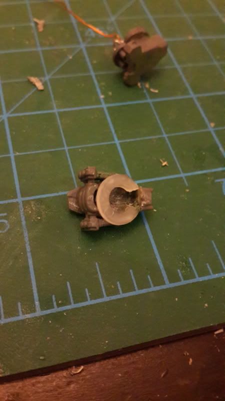
8. Test fit the LED into the hollowed out head. Do this multiple times until you have enough room to situate the light right up against the face plate. Nine times out of ten, you’ll find that you were mistaken about one dimension or another, and the LED doesn’t fit quite right. Keep hollowing it out to make enough room. This is all about trial and error, so just keep at it.

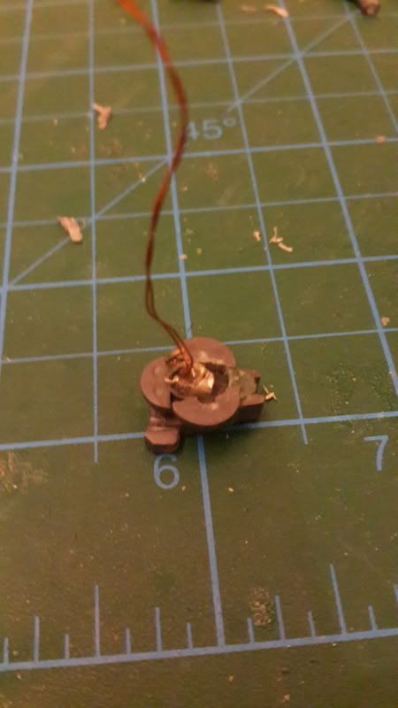
9. Once the LED fits into place and you are happy with the light you’re seeing out of the eye (you DID remember to test your LED, right?), it’s now time to attach it.
10. Keep your battery on hand for this part. Apply a fairly generous dollop of gel glue to the inside of the head. The gel’s thicker consistency fills the gaps between the LED and the rough, uneven surface inside the head. Press your LED into the desired spot, being sure to press the bulb up against the face plate for maximum light output.
11. Wait a few seconds for the glue to stick. Don’t rush this.
12. Now that the LED is seated in place and the glue is half-dried, it will hold up to you putting it down and sticking the battery between the legs to test out the LED. You want to make sure first that the LED still works, and second that the right amount of light is getting through the hole.

13. If you don’t like the positioning, the glue is still only half dried so you can adjust the LED slightly with no problem.
14. Don’t worry if glue gets on the bulb of the LED. It dries semi-clear anyway, so it won’t dull the light too much.
15. If a bunch of the gel glue got into the eye hole, you can either leave it (slightly reduced light, which is a good or bad thing depending on your preference), or you can take your pin vise and drill the hole out again after the glue has completely dried. Either way is fine.
16. Take a quick picture and put it up on your project log to brag about it and impress all the interwebs!
NOTE: If you’re building a Tael head, or any other style of head that involves gluing the target lock onto the front of the crisis head, you will want to do the following. Before you attach the target lock to the face, carve out the entire inner surface of the face and the inside of the head. Now that you have a hollowed out face, attach your target lock to the head as normal. Once you’ve attached it, take your pin vise and drill through the largest of the suit’s eye lenses, opening the hole up to about the size of the 1.5mm drill bit. This will let you put the LED right up against the target lock for an intense glow.

Wow! That was a long list, I know. Some folks out there have done enough conversion work that some of the steps will seem superfluous. That’s cool, more power to you guys, the big dogs of modding. But this guide is meant for total beginners as well, so I made sure to cut them some slack and explain everything in full detail.
So now, all the gods willing, what we have is a single LED shining triumphantly out of the Crisis suit’s eye. Awesome! Now, be absolutely sure that you carve out a big hole in the neck of the suit to let the wire down into the torso. In most head conversions, you can’t see the neck at all, so don’t worry about making it too neat. If nothing else, you can fix it with a GS patch later on.
But what if you don’t want your LED in the head?

4b. “IRON MAN” CHEST LIGHT
You will need
Same as above, but also a circular bit, as explained below

It is okay, and I mean, perfectly permissible and encouraged, for you to put on some Black Sabbath during this part. No one will blame you.
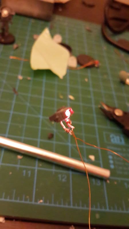
This method is actually quite a bit simpler than putting the light in the head. Since the space you’re working with isn’t so small, you can use a larger LED for this, so a 3mm LED is just fine. Take your drill and put a hole right in the center of the suit’s chest, right in the little box in the center. You want this hole to angle slightly downward, because that light is going to be blindingly bright if you angle it up at the players, and that will not make you any friends.
1. You can drill this hole out to 1.5mm like the one in the head, or you can go up to 2mm or so. Either way, it’s gonna be bright.
2. Test fit the LED into the hole. A little bit of the LED should protrude from the chest, but not too much. Make a mental note, or failing that, take your hobby knife and scratch a mark into the surface of the LED to show where it hits.
3. Now, take the LED out and mix up a little bit of green stuff.
4. Roll a bit of GS into a long “snake” and wrap it around the LED at the point where you made the mark. This is going to help the LED adhere to the chest-hole. That’s a technical term.
5. Apply glue to the GS ring and plug the LED into the chest hole.
6. Allow the glue to dry some, then test the LED to make sure you didn’t break it.
7. Attach a circular bit to the chest (See Below)
Right now, you have a super bright LED shining out of the chest of your suit. It looks really cool, until you go to game with it. Then it’s obnoxious and blinding. You’ll have a splitting headache by the end of the game. To fix this, we’re going to add a baffle to the light, a round bit to blunt the knife edge that is the LED.
Choosing your round bit: You have a few options here. Any Tau modder worth his salt has probably heard of a company called Kotobukiya, whose products are available from Hobby Link Japan (http://www.hlj.com). They sell sprues of option parts and details for Gundam models, and these are invaluable resources. One of the most useful things they sell are simply called “round mold” and it’s a sprue of tubular plastic bits. You can either grab one of those and file it down to a slight angle, or you can take the barrel of a multilaser or a lascannon and drill it out, cutting off just the very end of the muzzle to use. Either way, you want it to block a lot of the light that would normally be directed upward at the players’ faces.
(PICTURE)
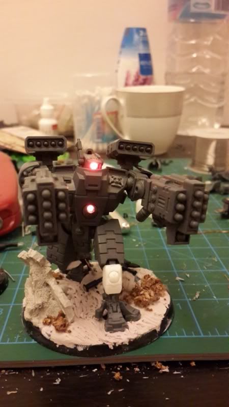
Situate that round bit so that the light is directed at a slightly downward angle. You will not lose much of the brightness, but you will eliminate the headache altogether.
NOTE: The chest on the Broadside model is much thicker than the Crisis suit’s. You don’t have to add a baffle to that light. You can drill it straight into the circular portion of the Tau emblem on the suit’s chest, and the extra thickness of the chest plate will shield the excess light from the players' eyes.


So now, what we have is a recipe for a single LED somewhere on the model. But we still don’t have power running to it from that base you built in Section 2. That’s why we’re moving on to…

SECTION 5
PUTTING IT ALL TOGETHER

You will need
The powered base you built in Section 2
Your model kit, ready to assemble
Hobby Knife
Pin Vise and Drill Bits
Soldering Iron and Solder
Green Stuff

You have a few different options of how to get the wire from your LED to the battery in your base. The way I normally do this is to carve a hole into the hip socket of the crisis suit and run it down through the leg. If you’re not concerned with appearances, you can just run the wire straight down to the base. But you are concerned with appearances, or else why would you be trying this stunt at all?
0. Make sure you have plenty of slack in your wire so that it won’t be pulled tight when you get it to the base.
1. Drill out one of the hip sockets of your suit. Either side works, but I like to put the wires on the side where the leg will be straighter (assuming you’ve cut and reposed the legs at all). This makes it easier to get the wire down through the leg.
2. Using your hobby knife, slice off the inside of the leg’s ball joint. It doesn’t have to cut off too much, you just want to make a flat surface into which you can drill easily.

3. Start with your pin vise and drill a nice big shaft into the ball. Be careful not to come out the other side, but if you do you can always just fix it with GS.
4. Hollow out the ball joint using your hobby knife in the same fashion as the head in Section 4a.

5. Flip the leg over. Using your 0.5mm drill bit, drill upward into the knee joint of the crisis suit as shown:

6. Continue drilling until the drill bit emerges into the hollow of the ball joint. Carve a little more of the plastic away in that area so you can get to it easily with the wire.
7. Feed the wire from your LED through the hole in the hip socket and then close up your chest. You might not want to glue it shut just yet, in case you’ve made a mistake.
8. Try to feed the wire into the narrow channel left by the drill that leads down to the knee joint. If you can’t get it in, try one of two things. First, make sure that the ends of the wire are twisted together tightly so that they take up less space and are more rigid, that should help get them in the hole. Or second, drill back up through the knee with a larger drill bit. Repeat until you get it through, then feed the wire all the way through the knee.
9. It is now safe to close the chest and attach the leg. You might need a wad of GS for the leg joint since you carved a lot of the material out.
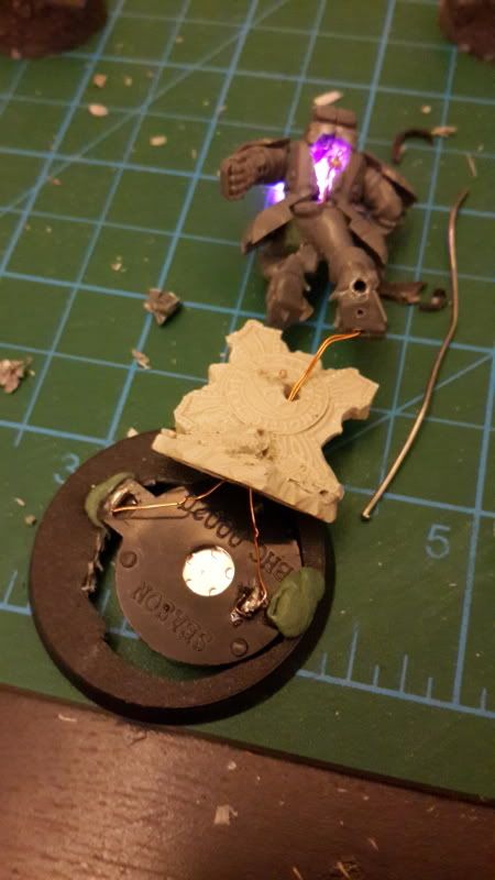
10. Before you glue the foot to the base, solder the wires to the battery leads sticking out of the top of the base. Be sure to put the battery in to test which lead is the correct one for each wire before soldering into place.
11. Repeat the steps of the Idiot-Proof Soldering method I described in Section 3. This time you are wrapping the wire around the battery leads. Solder each wire to the correct lead, but make sure you take the battery out when you do your soldering.
12. Seriously, not taking the battery out will screw up the whole job. The clip will become loose and wobbly and your lights won’t stay on. It’s kind of a nightmare to fix. Trust me.
13. Now that your wires are attached to the base, put the battery back in to test that it works. If it doesn’t, trace your steps backwards and figure out what went wrong, then start over from that step.

14. Once you’ve tested it successfully, you’re ready to attach the model to the base. Simply wrap any excess wire around the model’s ankle and glue the foot to the base. Attach the other leg for stability and you’re good to go.
15. Now, you’ll notice there is an unsightly wire protruding from your model’s knee, and ruining the illusion. Hide it by gluing a Fire Warrior shoulder pad or similar piece of armor over the shin. It looks better like that anyway.
16. Cover up the battery holder with your choice of basing materials. I like to start with a foundation of epoxy putty and add bits and flock to that. Regardless, you need to hide the battery holder or the illusion is ruined.


Congratulations! Your suit is now a glowing LED badass! What more could you ever want?
Oh…you do want more? You say you want multiple LEDs in your model? You want your guns to light up as well? You want multiple eyes and odd shaped heads? You even want your model to fly while glowing? Well, I suppose we could do that. Anything is possible in PART 3: REVENGE OF THE SOLDER!!!


APPENDIX

Depending on what type of model you are trying to light up, you may have a hard time getting the wire to run up the inside of the leg. The first time I ran into this problem was when I was lighting an XV25 Stealth Suit. There is no one straight line that goes all the way from foot to hip. In cases like these, you need to carefully cut at the joints and hollow out the parts so that the wire can pass up one part and into the other. Once you've passed the wire through the whole leg, use a small amount of GS and gel glue to seal it back up. Clean up any exterior damage with your hobby knife and you're good to go. This same method works for arms, strangely shaped bodies, or any other such situation where you need the wire to go through a maze-like section of a model.


PART 3: REVENGE OF THE SOLDER

Still reading, eh? If I had to guess, and I don’t have to but I will anyway, I’d say that you’re interested in doing some more impressive stuff. Okay, we can do that. But be forewarned, once we get going and reach 88 miles per hour, it’s gonna get freaky.

SECTION 3-1: WORKING WITH MULTIPLE LEDS


You will need:

LEDs
Wire
Soldering Iron
Solder
Soldering Armature
Clippers
Hobby Knife
Coin Cell
Mountain Dew
Cheetos


Let me start by saying that, as complicated as it might seem, installing a single LED is really the easy mode of this kind of project. Now we’re getting into some rocky territory. This section isn’t going to teach you the specifics of how to wire your guns and jets and such. This is a step on the way, and I’m gonna tell you how to rig up multiple LEDs to run off one battery.
As I mentioned in a previous section, not all LEDs are exactly the same. I could get very technical, but to keep it simple just make sure to test all the LEDs you want to run beforehand. Test them together by sliding their legs down around the battery and holding them there while you slot the others on. You may notice that specific sizes or colors refuse to work with one another, or that you have two or more distinctive groups that do work together. The reason for this is called forward current value, and there’s this math formula with lots of squiggly lines involved so screw that. Just prod your way through your LEDs and figure out which ones work together. If you got all your LEDs in the same size and color, then you don’t even have to worry about this. If you’re wondering, my variety pack worked with (Blue, White, Pink) and (Yellow, Orange, Red, Green) together. But there’s a workaround that I’ll tell you about in another section. I’m such a tease, I know.

There are two ways to wire lights up together on one circuit, called Parallel and Series. For whatever reason, the more technically inclined seem to love Series configuration but I find it needlessly complicated. Parallel is how I roll, because it’s much simpler to keep track of.
Parallel means that you’re taking multiple LEDs and wiring all the negative legs together, and all the positive legs together. So, let’s assume we’re wiring up 2 LEDs for now (Chest and Eye, for example).
There are two methods I’ve used to go about this.

Method 1; The daisy chain.
This method involves wiring up an LED, then wiring another LED onto your LED like it’s one of those Xzibit memes (yo dawg). It works best when you are only connecting two LEDs to one another.
0. Complete the process of wiring a single LED as described in Part 1 (LED 1).
1. Using your coin cell, identify which leg of the LED is negative and which is positive. You may find it helpful to give one leg or the other a bend so that it is plainly marked for the future. Do the same for your second LED.
2. Connect wires to the second LED just as you did with the first, following the guide from part 1 (LED 2).
3. Take the wire attached to the negative leg of LED 2 and solder it to the negative leg of LED 1
4. Attach the positive wire to the positive leg in the same fashion.
5. Test your circuit to be sure that both LEDs light up by touching the free-hanging wires to the battery on the correct sides.
6. If both lights come on, congratulations! If not, go back and hunt down where a connection might be loose, and stick the battery between the legs of each LED to see if one might have broken. Once identified, fix the problem.
7. Mount the LEDs in the head and chest using the methods described in previous parts, but make sure you only mount one at a time or you risk making a mess of things.
8. Eat your Cheetos and Drink your mountain dew to give the glue and GS time to set, and then mount the second LED.
9. Connect the loose wire to the powered base you built in Part 1, and you are done!

Wasn’t that easy? But what if you want to get really freaky? If you mount 3 or 4 LEDs in a single suit using the Daisy Chain method, they tend to turn into this massive sprawl of interconnected wires going this way and that, and you have to pay attention to which one you wire to which. You wind up with the right arm wired to the head, the head wired to the chest, the chest wired to the left arm, the backpack wired to the right arm…it gets jumbled. That’s why I worked out the next method.
HOWEVER, that method involves how to run wires for your guns and backpack as well. So before I explain that method, let’s tackle the big question of lighting the guns.


SECTION 3-2
WIRING YOUR GUNS


Let’s talk about how to get LEDs wired into your guns. Now, if you’ve been reading this guide and trying out some of the procedures described within, you might be looking at your guns already and thinking about ways to get them lit up. Unfortunately, the guns are not nearly as straight forward as the head and the chest. In fact, certain guns (I’m looking at you, plasma gun) are just a nightmare and you’ll see why when you actually try to wire it up. There just isn’t enough space inside these tiny guns to get the job done, most of the time.
We’re going to start off with Fusion guns and then move to Plasma guns so that you can learn how to do the job properly, or at least without ruining too many bits in the process.

DRILLING OUT AN ARM AND PREPPNG THE SHOULDER
All attempts at wiring a gun begin with running the wire down through the arm of the crisis suit. The arms are fairly simple to drill out if you are careful. The chest can be surprisingly frustrating though, because of the way it fits together. Be patient and follow the instructions below.
0. Clip the very tip of the shoulder ball joint to make a flat surface, just as you did when drilling into the hip joint earlier in the guide.
1. Drill a hole straight through the ball joint and into the chest cavity of the crisis suit’s chest.
2. Test fit the torso together and you’ll notice that the back of the torso slots in over the place you just drilled, so carve out a portion of that surface to allow the wire to reach the arm.
3. Repeat the process for the other side.
4. Decide how your gun will be mounted (side mount or under slung, underslung is easier)
5. Cut the arm at the shoulder joint, so that the forearm and elbow are a separate piece. Clean up any rough edges from the cutting.
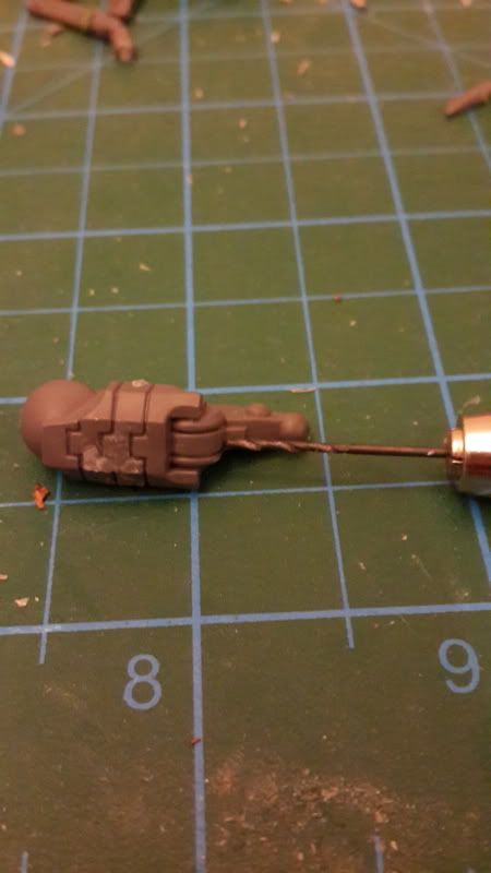
6. Drill a hole in the bottom of the shoulder socket so the wire can pass through it.
7. Now drill a hole up through the forearm using your 0.5mm or 1mm drill bit. The intent is to have the new hole emerge from the upper surface of the elbow joint, so line the drill up carefully when you do this step. Any mistakes can be fixed with Green Stuff later.
8. Once the hole is drilled, test fit the pieces together and adjust the holes as needed so that the wire can run straight through from the shoulder to your weapon without anyone seeing.


FUSION GUNS
You will need

Fusion blaster
1.5mm LED, pre-wired as in Part 1
Soldering Iron
Solder
Armature
Green Stuff
Hobby Knife
Coin Cell
Circular bit (see below)

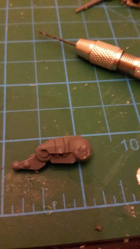
1. Cut the barrel off your Fusion Gun at the joint between the thinner part and the main body of the gun. Set the barrel aside.
2. Test fit the body of the gun onto the hole you drilled in the forearm. Make a note of how much of the surface is covered up when the pieces are fitted together, because you may need to mess up one piece or the other to make the wires fit properly.
3. Start by drilling straight into the body of the gun with your 1mm drill bit from the side you just cut. Drill in as far as the attachment point where you want the wire to come in.
4. Once that hole is drilled, flip the bit around and drill a hole into the body of the gun where you want the wire to enter, pointing towards the barrel. This should quickly meet up with the hole you drilled from the other direction.
5. Once the two holes meet up, hollow the area out a bit more with your hobby knife but remember to leave enough surface for the barrel to reattach securely later on.
6. Test fit the pieces together and feed the wire through to make sure it goes in easily without kinking up or getting stuck.
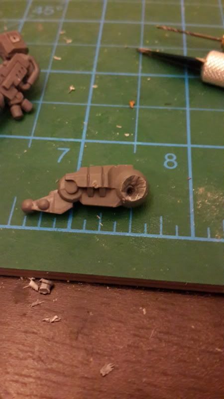
7. Now set the body aside and pick up the barrel. Shave off the nozzles at the end so that the face of the gun is flat. Now take your 1mm drill bit and drill a hole in the center of the barrel that runs all the way through to the other side. This will require patience on your part and you may find it easier to go in from the other side as well.
8. Widen that hole using your 1.5mm drill bit, being careful not to rupture the sides of the gun.
9. 1.5mm LEDs are actually about 3mm wide at the base, so you will need to use your hobby knife to completely hollow out the end of the barrel, leaving just enough of the walls to keep the piece sturdy.
10. Using your flush cutters or hobby knife, trim down the rectangular base of the 1.5mm LED so that it will fit into the hole you have prepared. Make sure that the legs have plenty of room and will not be forced to tough together when pushed down the barrel. Test fit and trim more until you are able to seat the LED all the way into the inside of the barrel.
11. Solder the LED to two long pieces of wire if you have not already done so. These will need to be long enough to go up the gun, through the arm and the shoulder, into the chest, and connect to your power circuit there.
12. Feed the wire all the way through all of these parts one at a time and seat your LED into the gun barrel with a bit of gel superglue. Once it’s in place and you’ve tested to make sure it still functions, go ahead and glue the gun to the arm, then the arm to the shoulder.
13. Feed the wire into the chest and solder it to the circuit there before you glue the arm or chest into place.
14. Fit a circular bit over the LED to act as the new nozzle for the gun, and to blunt the extreme light these LEDs will put out. I used some lens bits from Bandai that were made for Gundam kits, but you could use the barrel of a lascannon, multilaser or anything else you feel is appropriate. Fill the edges around it in with green stuff.
15. Smooth out any rough edges along the gun and fill any gaps with green stuff.
16. Repeat these steps for the other side if you are running a second Fusion gun.

Now, barring any catastrophic fail, you should have a crisis battlesuit with 4 glowing LEDs. One in the Chest, one in the head and one or two in your fusion guns.


PLASMA GUNS

Plasma guns gave me a very hard time when I first set out to light my crisis suits. When you attempt to tackle the problem yourself and really get into the nuts and bolts, you’ll understand. The Tau plasma gun is just a little too skinny to make this an easy task. Luckily, the plasma guns from the Broadside kit are significantly thicker than their crisis cousins. You’ll want to use those for lighting with LEDs.
Step one is obviously to acquire the guns, either from a bits seller or from a spare kit lying around. Then you’ll need to do the whole routine of making sure that all your LED colors are compatible, as I mentioned before, and that they all work. Once you’ve got that done and you’ve got the LEDs wired up individually, it’s time to get to work on your plasma gun.
Important note: You will want to clip the legs on the LEDs VERY short for this application, so short that they’ll be tougher to work with. The reason is that you don’t have much room for them in the body of the gun, and this will save you some serious headaches.

You will need:

Broadside Plasma Gun
Wired 3mm LEDs, legs cut very short
Hobby Knife
Green Stuff
Clippers
Pin Vise and drill bits up to 3mm in size

1. Separate the plasma barrel from the gun’s body. Carve away the thin section that normally connects the two.
2. Starting from the tip, drill into the plasma barrel using your 1mm drill bit. You may want to start the hole with your hobby knife. Drill completely through to the other side.
3. Starting from the flat side of the barrel, drill into it with your 1.5mm drill bit, about half way. Widen the hole using your 3mm drill bit, being VERY careful not to damage the bit. The barrel should be almost completely hollow by now.
4. Test fit your 3mm LED. You should notice that the entire bulb of the LED fits snugly inside the barrel now, with the exception of the flanged base (if applicable, some LEDs do not have the wider base).
5. You have two options at this point and it depends on your preferences. You can either leave it as-is and leave the base of the LED exposed, which will result in a bright ring of light at the base of your barrel as well, or you can conceal the entire LED inside.
6. If you choose to conceal the whole LED, carefully cut away most of the flanged base with your clippers and hobby knife. Do this gradually to avoid breakage.
7. Test fit again, and then hollow out the barrel very carefully with your hobby knife, being sure to remove only small slices at a time until the LED finally fits into the barrel entirely, leaving just the wires and legs sticking out. Test the LED with the battery, just in case.
8. Set the barrel aside and pick up the body of the gun. Clip away the peg that will attach the gun to the arm.
9. Starting from the front face where the barrel will attach, drill into the body of the gun with your 1mm bit, then hollow out the gun as much as possible with your knife and drill. You will need to remove a great deal of the face to which the barrel will attach, so that the legs of the LED can slot into the gun neatly.
10. Drill into the spot where the attachment peg used to be to allow your wires to go through the gun.
11. Test fit the barrel onto the gun. If the legs of the LED met resistance, hollow out the body some more and try again. Remember that at this stage you can spin the LED around within the barrel to change the orientation of the legs.
12. Once the Barrel assembly fits flush against the body of the gun, roll out a very skinny “snake” of green stuff.
13. Secure the LED in the barrel with a small amount of gel superglue, and remember to test-fit it again before the glue sets in case you need to make last minute adjustments. Test the LED with the battery to make sure it still works.
14. Eat your Cheetos and drink your Mountain Dew so that the glue has time to set.
15. Add a small amount of glue to the perimeter of the barrel. Run that skinny green stuff “snake” around the edge so that it will adhere easily to the body of the gun, then put a tiny bit of glue onto that.
16. Feed the wire through the body of the gun, and then seat the barrel flush against the body of the gun. Use the flexibility of the GS to very slightly adjust the barrel’s position, until you’re satisfied that it’s pointing straight in the direction you want it.
17. Touch the wires to your battery to give the LED a final test.
18. Do NOT go in with your hobby knife and try to remove the excess GS. Do NOT try to patch the hole around your barrel assembly right now. The GS is too soft and you have it just how you want it.
19. Set it down and walk away. Let the green stuff cure.
20. I mean it. Come back tomorrow.
21. Sleep.
22. Is it the next day? The green stuff around the barrel is now cured. NOW you can go in with more GS and fill in all the holes you made and repair the visibly scarred parts of the gun. NOW you can use your hobby knife to remove any excess GS from the barrel’s attachment point.
23. Run the wire up the arm and into the suit just as in the previous example.
OPTIONAL: Fiber Optics and Necron Rods.
You might not be satisfied with the light coming from deep inside the gun. You might want the light to shine right out the tip of the barrel. Okay, we can work with that. You have two options for this.
1. Fiber Optics. Stick a 1mm string of Fiber Optic wire down the barrel until it touches the LED. Glue it in place (very little glue) and then clip it off at the desired length. You can either clip it off flush with the barrel or you can leave 1 or 2mm sticking out. If you leave some sticking out, you can touch the tip of your soldering iron to the tip of the optical wire, and it will do this cool mushroom effect (experiment before you actually try this on the model, to get a feel for it). The result will be a wider-shining light, and the mushroom head will contract down against the barrel. Hard to explain, hard to photograph, but if you experiment with this you’ll see exactly what I mean in person.
2. You can widen the hole in your barrel to 2mm and then shove a green necron rod down the hole, all the way til it touches the LED. Clip the rod so that it is flush with the barrel, and the LED light will be shining brightly out the tip. If you have a white LED, this will tint the light green. Other colors are almost completely unaffected.

APPENDIX:
With all the talk about saving space and how tiny the plasma gun is, you might be asking why I didn’t use the 1.5mm LED. The problem is that the barrel is quite long. The base of the 1.5mm LEDs is rectangular, and you wind up trying to put a square peg in a round hole. It never quite sat the way I wanted when I tried it, and the light was always cocked to the side, resulting in a dim glow from the barrel instead of a bright light. You can try it with a 1.5mm LED, and by all means show me how yours comes out if it works for you, but I found that the 3mm round ones fit very neatly in the barrel.


HYDRA WIRING

Now that we got through the basics of how you’ll want to wire your guns, I feel I should tell you about the other wiring method I managed to figure out. Personally, don’t like it as much but it can be useful if you’re working with a lot of LEDs.
Wiring Method 2; The hydra.
This method is more complicated and can be a bit of a headache, so just be forewarned of that. I find this method works better when I have to manage a lot of LEDs in a suit.
1. Cut off four lengths of wire (or however many LEDs you have) and strip one end of each of them.
2. Cut off a fifth wire that will connect the rest to your base and strip one end.
3. Twist the stripped ends of the four LED wires together very tightly, so that they stay together securely.
4. Wrap the stripped end of the base wire around this twisted cluster.
5. Solder the entire cluster generously so that all the strands are permanently connected.
6. These wires will all go to the positive legs of all your LEDs, while the one lone wire snakes down to the positive end of your battery holder.
7. Repeat the process a second time, so that you have a second wire cluster to connect to all the negative legs of your LEDs, and the negative lead on your battery holder.
This can be very useful for wiring up a tank or the like, where all your LEDs are in one big compartment. It would also work well if you had a lot of LEDs in one part of the model and needed to connect them all to the circuit with one wire. Personally, it’s a bit of a hassle for crisis suits since you have to solder your LEDs after you’ve run the wire through the model. However, for completion’s sake I felt I should include this method so that you aren’t left wondering.


Automatically Appended Next Post:
Still to come: Additional effects, glowing fuel rods and muzzle flashes, more total insanity.

This message was edited 1 time. Last update was at 2013/12/12 01:49:57


IMPOSSIBLE IS RELATIVE
Boss, everything you make is gold.

Dubstep Tau, let there be LIGHT.
Blind them with SCIENCE, a tutorial series for adding LEDs and effects to your models.
Powerlifting and Plasma, a Romantic Comedy 
   
Made in us
Sadistic Inquisitorial Excruciator


Good Ol' Texas

Yes! Its finally up! Thanks so much, Bossfearless!

Lucarikx


Made in gb
Slippery Scout Biker


SPARTA

Cool,yes. Useful,yes. Completely,ridiculously insane. Yes

I play SM o not much use for these techniques

This message was edited 1 time. Last update was at 2013/12/12 19:12:45


Made in sa
Bane Lord Tartar Sauce


Saudi Arabia

Rory1432 wrote:
Cool,yes. Useful,yes. Completely,ridiculously insane. Yes

I play SM o not much use for these techniques


The techniques used in this guide are pretty universal, as far as how to solder an LED or hollow out a bit. To be honest, Space Marines are a million times easier to work with than Tau models (actual poseable models, big LED-friendly boxes for tanks, etc.). Tell you what, when I eventually work on some Space Marine stuff again, i'll take WIP pics and put up a separate article for Metal Bawkses

IMPOSSIBLE IS RELATIVE
Boss, everything you make is gold.

Dubstep Tau, let there be LIGHT.
Blind them with SCIENCE, a tutorial series for adding LEDs and effects to your models.
Powerlifting and Plasma, a Romantic Comedy 
   
Made in gb
Water-Caste Negotiator


Stratford on avon

I’ve been trying to make a nice shield gen for my tau but didn’t want the cables exposed this has shown me the best way MANY MANY thanks!!!

Careful I have CDO it’s like OCD but in alphabetical order LIKE IT SHOULD BE!!!!!!

Make it idiot proof and someone will make a better idiot.

4000Pts
3000Pts
1000Pts
2000Pts
1500Pts 
   
Made in ca
Grizzled MkII Monster Veteran


Toronto, Ontario

 bossfearless wrote:
You’ll burn your eyebrows off and never see the cat again.


Okay, awesome tutorial, but I've gotta say... a reference to The Rock?

Favourite post of the year. Well done.
   
Made in sa
Bane Lord Tartar Sauce


Saudi Arabia

Hey, it was one of the few movies with Nicholas Cage that he didn't ruin with his broad definition of "acting."

Don't be hatin'.

IMPOSSIBLE IS RELATIVE
Boss, everything you make is gold.

Dubstep Tau, let there be LIGHT.
Blind them with SCIENCE, a tutorial series for adding LEDs and effects to your models.
Powerlifting and Plasma, a Romantic Comedy 
   
Made in ca
Grizzled MkII Monster Veteran


Toronto, Ontario

Hating??

Hell no, I love that movie!

Just don't see it quoted very often 'in the wild'.
   
Made in us
Road-Raging Blood Angel Biker


Thanks for the time it took to do this. Great inspiration.

   
Made in nl
Deadly Dark Eldar Warrior


Excellent write up!
I just have one remark:
Please try to get some resistors in your schematic!!
The battery's will last much longer and the wires won't heat up as much.
Just put a single 100 Ohm resistor between the negative lead and the battery and everything is Electronically sound.
   
Made in us
Cackling Daemonic Dreadnought of Tzeentch


Ellenton, Florida

Great tutorial. Thanks!

Armies:  
   
Made in gb
Proud Triarch Praetorian


Great tutorial, will hopefully put your instructions to use one day.

However, I think you should try and Wire up one of these:


EDIT: images...

This message was edited 1 time. Last update was at 2013/12/23 15:18:31


Experience is something you get just after you need it
The Narkos Dynasty - 15k
Iron Hands - 12k
The Shadewatch - 3k
Cadmus Outriders - 4k
Alpha Legion Raiders - 3k  
   
Made in gb
Regular Dakkanaut


Devon, UK

This is awesome, good job!!!! I'm doing something like this with LED's and a Skyshield landing pad.

Painter not player.....yet. Check out my gallery!!!

http://www.dakkadakka.com/gallery/user/80991-DarkHero.html 
   
Made in sa
Bane Lord Tartar Sauce


Saudi Arabia

Thanks. I still need to go back through and pepper in a few more pictures That's going to happen when I do my next round of builds, though, so that I can take some step-by-step WIP pics to fully illustrate everything. And also, I need to get pics of the "glowing fuel rods" build as it comes together.

IMPOSSIBLE IS RELATIVE
Boss, everything you make is gold.

Dubstep Tau, let there be LIGHT.
Blind them with SCIENCE, a tutorial series for adding LEDs and effects to your models.
Powerlifting and Plasma, a Romantic Comedy 
   
Made in us
Fresh-Faced New User


Nice to see another led tutorial up. Very well done and trust me... I know there is little info out there. The tutorial series by devinsdad you mentioned is mine, done a while back. Currently I'm working on doing an rc land raider and brother I wish I could find a tutorial on that. I am curious though I'd like to see a pic of the finished underside of a base with your method cause I was never satisfied with my hot glue and felt.solution. personally... I figured the real solution would be investing in mold making stuff and sculpting a base with a battery holder built in and casting it

   
Made in us
Road-Raging Blood Angel Biker


Some quick tips I've found following this tutorial:

Wrapping the wire around the legs of the LEDs seems to suck, all the time. I've tried with and without the armature, using needle-nosed pliers and a few other ideas and nothing seems to do this reliably and easily.

The LED gets very hot nearly instantly when the soldering iron is touched to it. Yes, obviously it's going to get very hot because of the iron, but I was surprised at how quickly it happened and that my entire LED was too hot to touch, not just the parts close to the iron.

Sometimes you need a hole bigger than your biggest drill bit. I haven't found an easy way to do this beyond drilling multiple holes next to each other and using a knife to carve out any remaining material.

Technically you're not soldering correctly. Technically I'm not sure it really matters, and soldering correctly takes significantly longer and the difference is very noticeable with a low wattage soldering iron. However, a problem I have run into with your technique is that sometimes the solder clumps only to itself, and just drips off of the wire clump instead of getting caught. For some reason I couldn't get it to flow reliably into the clump and usually took several tries to get a good solder using your technique.

Thanks again for the tutorial.

   
Made in sa
Bane Lord Tartar Sauce


Saudi Arabia

Ricter wrote:
Some quick tips I've found following this tutorial:

Wrapping the wire around the legs of the LEDs seems to suck, all the time. I've tried with and without the armature, using needle-nosed pliers and a few other ideas and nothing seems to do this reliably and easily.

The LED gets very hot nearly instantly when the soldering iron is touched to it. Yes, obviously it's going to get very hot because of the iron, but I was surprised at how quickly it happened and that my entire LED was too hot to touch, not just the parts close to the iron.

Sometimes you need a hole bigger than your biggest drill bit. I haven't found an easy way to do this beyond drilling multiple holes next to each other and using a knife to carve out any remaining material.

Technically you're not soldering correctly. Technically I'm not sure it really matters, and soldering correctly takes significantly longer and the difference is very noticeable with a low wattage soldering iron. However, a problem I have run into with your technique is that sometimes the solder clumps only to itself, and just drips off of the wire clump instead of getting caught. For some reason I couldn't get it to flow reliably into the clump and usually took several tries to get a good solder using your technique.

Thanks again for the tutorial.


Okie doke, lots of good questions here. I'm gonna go through one at a time and see if I can offer advice.

1. Wrapping the wire. The method I have found to wrap the wire around the LED easiest is like this: Put the LED bulb in the armature clamp so you have both hands free. Now, the tool I use to actually wrap the wire is the back of my hobby knife. It's thin enough to get into the tiny area and you don't have to worry about accidentally cutting the wire if you use the flat side. I pinch the wire to the LED leg using my fingers to keep it in place and I methodically bend the wire around it a little bit at a time. Once you get the method down, it works great nearly every time.

2. Hot LEDs: This might sound like a condescending answer, but it's not meant as such. Don't heat up the LED. I know, worst answer ever. Just don't actually touch the soldering iron tip to the LED leg. It should really only be touching the solder. The solder melts, glops down onto the wire bundle, and usually sticks in it. Heating up the actual LED can cause it to fail, wasting all your effort, so it's best to avoid it altogether. Maybe you could also try switching to a lower wattage soldering iron or, failing that, just don't let it heat up as long.

3. Big Holes: Maybe get a bigger drill bit? How big a hole do you need, and for what purpose? My tutorial makes use of drill bits up to 3mm, which is also the largest size of any LED that I'm using. If you need a super large hole, well, you'll have to give me more details to let me know what it is that I'm advising you on. Most of the time if I need a bigger hole for some reason, I just enlarge it with my knife, as stated in the tutorial.

4. Troublesome solder: Solder sucks. It's like an annoying, silver, liquid jackass who wants to ruin your day. My best advice would be to get the kind of solder with the flux core, as it's easier to wrangle. After that, my advice is to let gravity do the work for you. Angle the armature so that the leg is slanted downwards, and the solder should flow down the leg and have some time to cool off and solidify in the wire bundle. Again, a low powered soldering iron lets this happen easier.

Technically, I know I'm not soldering technically correctly in a technical fashion. Technically. It's all very technical. Actually, this is more of an idiot's guide (as in written by an idiot, so you know you can do it). I believe that in the correct soldering method, you heat up the wire and the LED leg and then you heat up the solder and apply it. I know there are a lot more steps. That's probably the source of some of the problems you're facing, trying to do something right that's meant to be wrong.

IMPOSSIBLE IS RELATIVE
Boss, everything you make is gold.

Dubstep Tau, let there be LIGHT.
Blind them with SCIENCE, a tutorial series for adding LEDs and effects to your models.
Powerlifting and Plasma, a Romantic Comedy 
   
Made in us
Road-Raging Blood Angel Biker


1. I'll have to try that technique... unfortunately I did all 18 of my LEDs at once, before I posted. But it sounds promising.

2. Yeah, I only had to heat my LED for the soldering technique I was using. I'll go into that more in a minute.

3. My problem, really, is the models I'm converting. I'm using Dark Vengeance Ravenwing Bikers and knocking out the front light for an LED. The issue revolves around the fact the the front plate actually slides into place from the top and has to go in behind the bolters because they're a part of the bike frame.

The obvious solution is then to just push the LED farther forward, so all you have to bend to get the front plate into place is some wire. Unfortunately, the front plate is pretty narrow, meaning that some of the LED is still sticking out of the back of the plate.

This led me to the solution of carving out a large chunk of the top of the bike in order to give the LED space to slide in.

Further, while my LED is only 1.5mm wide, with its legs sticking out and the wire scrunches, it can easily reach 3mm. My largest pin vise bit is 2mm.

4. That is the solder I'm using, unfortunately.

5. With regards to technique, I tried both your technique and the "correct" way. Your way was much faster, but I experienced the "dripping" problem when I used your way, hence why I brought it up. This didn't happen when I soldered "correctly", but it took much, much longer.


Automatically Appended Next Post:
Also, this is the iron I'm using: http://www.homedepot.com/p/Hakko-6-Watt-Battery-Powered-Soldering-Iron-FX-901-P/204215959#

I bought it from Amazon which didn't show the wattage. I didn't realize it was that low.

This message was edited 1 time. Last update was at 2014/01/15 15:36:02


Made in nl
Water-Caste Negotiator


I really like lighted stuff , and I actually tau so this will come in handy if I'd ever want to do something like this, tnx! I use mostly forge world models and those plasma rifles are even more tiny not sure if those would be doable (its impossible to even fit a 2x1 magnet in those so for magnetizing them I just put in a 1mm wire which generates enough force to hold them up )

I didn't know that broadside pilots could use terminator armor though

1500, 100% WIP, 100% kick-ass
(dkok) 1500, 100% NIB 
   
Made in nl
Deadly Dark Eldar Warrior


I don't mean to highjack your thread i just want to share a little of my experiences.

<rant>

If anyone has problems with solder dripping from the wires try this way of soldering (Semi-monkeyproof):

Fix the wire you want to solder to the LED in an armature or tape it to your desk so it sits with the stripped part someway from the table.

Hold your soldering iron to the stripped part of the wire and wait till the wire is heated up (2 - 5 seconds) then quickly pass over the wire with your solder so it is gently coated. (Turns silver)

Wait till it is cooled of for a bit and do the second wire.

Next fix your LED to the armature/desk so you have good acces to the legs.
Use the same skillset you used for the wires on the legs for the LED. Just don't hold the iron to the LED longer than a second or 3 (you might damage it).
After the legs are coated in solder cut them to length.

For our next trick we will now combine the wires with the LED!

Since both the wires and the LED are coated in solder you only need 2 hands! keeping the LED fixed in the armature hold the wire against the leg and gently touch the soldering iron to the connection and they will flow together in perfect unison

Now you have a connection good enough for small electronics!

</rant>

Keep on shining!

   
Made in us
Fresh-Faced New User


Hate to burst your bubble guys but the only answer to soldering is practice. It is a skill. I have never wrapped wire on my models and never will. On the tau you might be able to get away with it but the majority of the ones I lit up have barely enough room for the led, let alone any excess wire. The only secrete here is practice. When I did my first models, I had a bit of experience in soldering, but no where near what I can do now. I don't remember I'd I show myself doing any in my chaos Lord video, and not to brag, but I can now do a nearly perfect solder on a 3Mm led with almost no wire stripped back, maybe1 to 2mm. This is important if you intend on bending that wire cause it's hella easy to short it out if you have too much stripped.

My suggestion is to youtube soldering techniques and practice. By the time you've done 50+ models you should have it down pat


Ya, just looked at my video and part two shows me soldering a led. The key is to have the two wires touching and just touch some hot solder.too.them coating both wires

http://youtu.be/7oTGaWpu2Zc

This message was edited 1 time. Last update was at 2014/01/17 06:54:50


Made in sa
Bane Lord Tartar Sauce


Saudi Arabia

MoD_Legion wrote:
I really like lighted stuff , and I actually tau so this will come in handy if I'd ever want to do something like this, tnx! I use mostly forge world models and those plasma rifles are even more tiny not sure if those would be doable (its impossible to even fit a 2x1 magnet in those so for magnetizing them I just put in a 1mm wire which generates enough force to hold them up )

I didn't know that broadside pilots could use terminator armor though


I'm not sure what you mean by the terminator armor comment at the end, maybe you could explain? Anyways, my suggestion to you as far as lighting up plasma rifles is to spend a few bucks on a bits site and get a bunch of the ones used by the Broadside kit, because they have the largest diameter. Alternatively, you could get a little bit crazy and use plastic Imperial plasma cannons,


As to your question about magnets, that's currently under development. Keep in mind that the battery is in the base of the model. The LEDs do not just light up on their own. I'm working on developing a system and writing up a tutorial for (VERY carefully) using magnets to complete a circuit and providing LED/swappable parts, which I have never seen done before. I'm a trailblazer like that.


Automatically Appended Next Post:
FaceofChaos wrote:
Hate to burst your bubble guys but the only answer to soldering is practice. It is a skill. I have never wrapped wire on my models and never will. On the tau you might be able to get away with it but the majority of the ones I lit up have barely enough room for the led, let alone any excess wire. The only secrete here is practice. When I did my first models, I had a bit of experience in soldering, but no where near what I can do now. I don't remember I'd I show myself doing any in my chaos Lord video, and not to brag, but I can now do a nearly perfect solder on a 3Mm led with almost no wire stripped back, maybe1 to 2mm. This is important if you intend on bending that wire cause it's hella easy to short it out if you have too much stripped.

My suggestion is to youtube soldering techniques and practice. By the time you've done 50+ models you should have it down pat


Ya, just looked at my video and part two shows me soldering a led. The key is to have the two wires touching and just touch some hot solder.too.them coating both wires

http://youtu.be/7oTGaWpu2Zc


Easy there, bro. This is a basic guide, not the advanced class. This is specifically meant for people who have zero experience, to get them started. Or for people who really only want to light up a couple of centerpiece models. 50+ LED models is at least a couple of armies' worth, so it's unlikely that a lot of people using this guide will ever go quite that far.

This message was edited 1 time. Last update was at 2014/01/17 09:07:29


IMPOSSIBLE IS RELATIVE
Boss, everything you make is gold.

Dubstep Tau, let there be LIGHT.
Blind them with SCIENCE, a tutorial series for adding LEDs and effects to your models.
Powerlifting and Plasma, a Romantic Comedy 
   
Made in us
Fresh-Faced New User


Didnt mean to come off rude, sorry about that if I did, its just the guy was asking about specific soldering tips and if he goes with the wire wrap method, it will only work on larger models. By all means, if this is what gets the job done, every time I've given advice, I always say that the most important thing is "whatever works for you". I can tell you how i do it all day long, but if I do something that doesnt work for your methodology, then it probably will never work and you might just end up better off doing something different anyway.

I will admit I havent lit up a tau yet (other then blowing them up on the board.. hehe..) but from what I've seen, they seem like good canidates on how to learn to do this sort of thing. Plenty of logical places to put lights and more room then most other models to work in.

Lastly, dont kid yourself, 50 models goes by fast. If your plan is just one or two centerpiece models, sure, but if you get the wild hair like I did and say "hey, what if my WHOLE army did that!" next thing you know, your at 100+ and you have everything from flashing eyed terminators to a rhino painted like the general lee that is complete with a horn that plays dixie.

This message was edited 1 time. Last update was at 2014/01/19 03:19:19


Made in nl
Water-Caste Negotiator


 bossfearless wrote:

I'm not sure what you mean by the terminator armor comment at the end, maybe you could explain?


On the left breastplate there is something that imho kinda looks like a crux terminatus, thats what I meant with it.

1500, 100% WIP, 100% kick-ass
(dkok) 1500, 100% NIB 
   
Made in us
Been Around the Block


Great post, thanks for sharing your work
   
Made in us
Road-Raging Blood Angel Biker


Some more things I've run into:

1. For making bases, hot glue is much faster that putty, but messier and harder to work with.

2. Carving up bases is kind of tedious. I wish there was a "hot wire cutter" equivalent for plastic.

3. Not all coin cell holders are built the same. Mine seem to be about three times the height of a base.

   
Made in sa
Bane Lord Tartar Sauce


Saudi Arabia

Ricter wrote:
Some more things I've run into:

1. For making bases, hot glue is much faster that putty, but messier and harder to work with.

2. Carving up bases is kind of tedious. I wish there was a "hot wire cutter" equivalent for plastic.

3. Not all coin cell holders are built the same. Mine seem to be about three times the height of a base.


I've also found that hot glue is much quicker than putty for seating the coin cell holders in the base. It's easiest if you can get yourself a cordless hot glue gun. I just got myself a rechargeable gun and it's so much more convenient than having to plug it in and such every single time, plus you don't have to fight with the cord the whole time. As for cutting up the bases, I got nothing there. I think this is a case where we're stuck doing things the tedious way.

Now, about the coin cell holders, you are completely correct that they are not all the same. That's why if you read the parts section, I specifically recommend the Keystone 103 or 106 model. These are a very appropriate size for a miniature base.

IMPOSSIBLE IS RELATIVE
Boss, everything you make is gold.

Dubstep Tau, let there be LIGHT.
Blind them with SCIENCE, a tutorial series for adding LEDs and effects to your models.
Powerlifting and Plasma, a Romantic Comedy 
   
Made in us
Road-Raging Blood Angel Biker


Yeah, I was impatient with regards to the coin cell bases and went with the ones that qualified for prime because I didn't think it would make that much of a difference. Bad idea.

I'm at the point where everything is connected and working, and the model is soldered to the base. Now I need to cover the coin cell holder. How exactly do you do that? I know you say you use putty... but do you just basically mash enough over the holder to cover the entire thing and then go from there? That seems like a lot of putty per base.

Also, the coin cell holder is uneven on top because of the soldering. Do you just build up a thick layer of putty on top then?

   
Made in sa
Bane Lord Tartar Sauce


Saudi Arabia

When I say cover the base with putty, I don't mean Green Stuff. Go down to the plumbing aisle in a Walmart or any hardware store and get a couple tubes of 2-part epoxy putty. Cheap, plentiful, and it cures in a couple minutes.

After that, yeah, you basically just mash it on there. I try to have an idea of what I want the base to look like beforehand, though, so that I can get it looking good.

Just put a nice thick layer over the coin cell holder and use that to level it out. One of the nice things about using this much putty is that it automatically weighs down the base, so your models don't tip over easily.

IMPOSSIBLE IS RELATIVE
Boss, everything you make is gold.

Dubstep Tau, let there be LIGHT.
Blind them with SCIENCE, a tutorial series for adding LEDs and effects to your models.
Powerlifting and Plasma, a Romantic Comedy 
   
 
Forum Index » Painting & Modeling Tutorials
Go to: