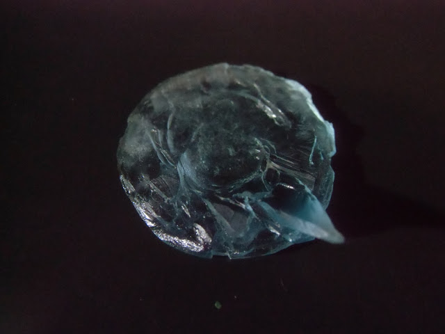
Switch Theme:

Powered Bases & Light-Up Bases  [RSS] Share on facebook Share on Twitter Submit to Reddit
»
Author Message
Advert


Forum adverts like this one are shown to any user who is not logged in. Join us by filling out a tiny 3 field form and you will get your own, free, dakka user account which gives a good range of benefits to you:
  • No adverts like this in the forums anymore.
  • Times and dates in your local timezone.
  • Full tracking of what you have read so you can skip to your first unread post, easily see what has changed since you last logged in, and easily see what is new at a glance.
  • Email notifications for threads you want to watch closely.
  • Being a part of the oldest wargaming community on the net.
If you are already a member then feel free to login now.


Made in om
Longtime Dakkanaut


Muscat, Oman

The original text is available with larger images on my blog.

It is hard to find a battery holder that will fit in a regular infantry model's base without having to cut a big hole in top - I've never found one anyway. However, after a lot of trial and error I settled on a way of fitting a battery into a standard round-lipped 30mm base without increasing the height.

Now this is a fairly labour-intensive method so if you're willing to build up the height a few mm then you don't need to bother with all of this as you should be able to just cut a hole and fit an off-the-shelf battery holder in place. One advantage of my technique however is that you can use standard base-toppers, and even illuminate clear base toppers if you wish.

It's probably not the best way, and it's probably not the easiest way, but it's what works for me. So as much as a part of me wishes to preciously guard the secret like Gollum and the One Ring, I figured it's not exactly so complicated that other people couldn't figure it out for themselves. But by writing a tutorial I get to claim credit for other people's creations... MWAHAHAHAHAAAAAAAAAAAAA!

Ah-hem. Anyway, here's how I do it, broken down as clearly as I can. I shall describe the process primarily from the point of view of building a light-up base as that's the more involved version. Where needed I will describe what to do differently if the LEDs are to be in the model itself.


Step 1: The Parts
Spoiler:
I actually use parts from two different battery holders. I typically buy a bunch of these two types off Ebay:


Now one thing that I've found is that some of these use a magnetic alloy and some use a non-magnetic alloy. You can see in the picture below that a magnet sticks to one and not to the other. It's important to use the one that DOES attract a magnet: my first few bases used the non-magnetic kind and they didn't light up reliably. The magnetic kind just seems to work better as a spring I guess.


Use a pair of needle nose pliers to pull the metal bits out. We need one piece from each - the two in the middle in this photo:


Step 2: Preparing The Base
Spoiler:
If you're using a standard PP-style 30mm round-lipped slotted base, you'll want to plug the slot with putty or by gluing in a carefully cut piece of plasticard. I've picked up some non-slotted Malifaux bases, but they are actually thinner than PP bases so there isn't enough room for everything inside. And obviously don't get the bases with the deeper recesses either.


Most bases have various details and projections on the underside:


We want a flat surface to work on, so cut or sand off all those projections. I like to slowly carve them off using a chisel blade. The only chisel blades I've found that fit a regular hobby knife are from a company called Olfa. Again, I just buy them off Ebay.


Step 3: Planning
Spoiler:
Now that we have a flat surface to work with, we want to plan where everything is going to go. Things to consider include the battery, a switch (if you plan on adding one), magnets (if like me you like to magnetise your bases), the positions of LEDs or wires connecting to LEDs in the model, and pins if you're planning on pinning the model to the base. It's especially important to figure out anything that depends on the model itself as these tend to have the least flexible positioning.

It's probably a good idea to mark planned positions with a marker if you need that level of precision - it depends on how specific things need to be placed I guess. If you know exactly where your model will sit you can drill holes into the base for pins and wires at this stage.


Step 4: The Battery Holder
Spoiler:
The typical 30mm 
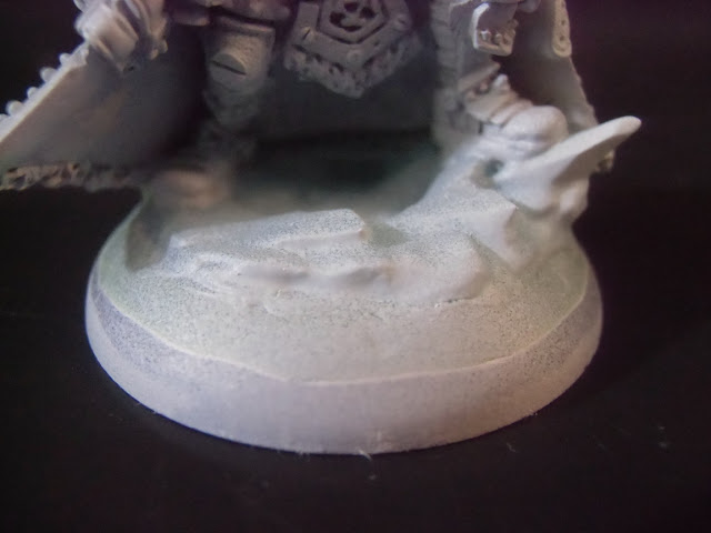
PP base is not quite deep enough for the components I'm using, so I will usually scrape or sand away a depression to give that tiny bit of added depth. This isn't always essential as I usually file the bottom of the base flat when everything is finished anyway, but taking away a bit of plastic early on is easier and usually better than taking away metal later.

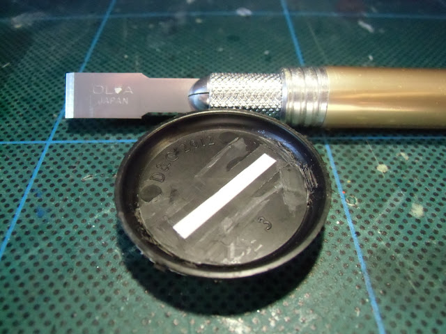
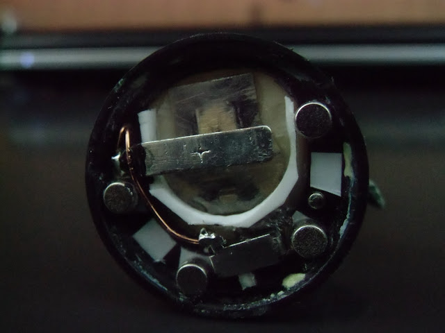
It's not obvious, but if you look you will see in this photo that I have carved out a shallow depression for the battery. I actually did this by scraping away plastic using the same chisel blade.


A good way to check if you've carved deep enough is to lay all the components - the battery and the two electrodes - on top of each other and then look at the base from the side to see if they protrude.


The next few bits are only needed if you are building a light-up base, you can skip them if you only need the base to hold the battery.

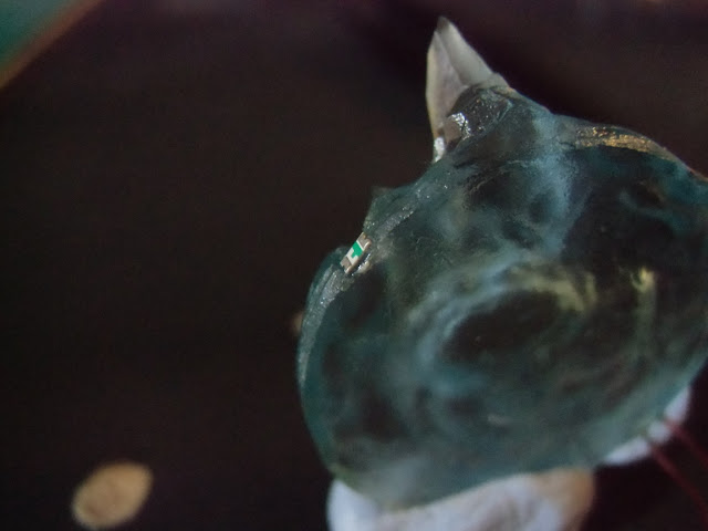
I actually scraped away a little bit of material around the rim for wires and LEDs using a small round file, but I'm not sure it actually mattered so you can probably skip this.


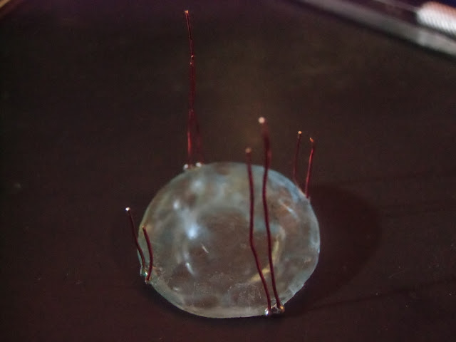
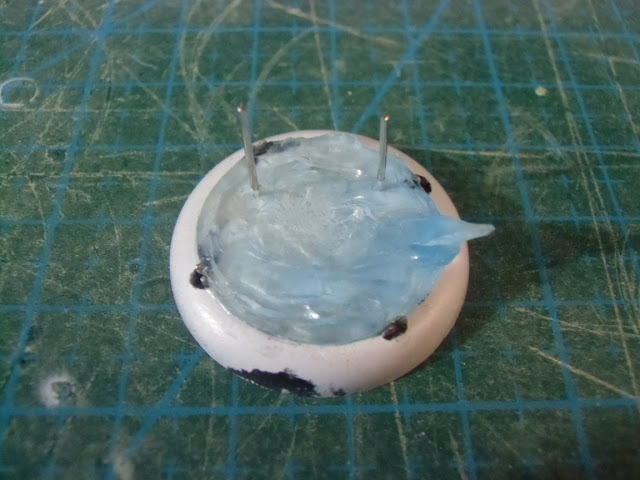
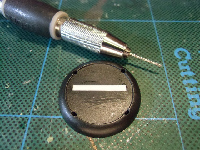
What is important though is to drill some holes around the rim that the LEDs will fit into. I used four for this 30mm base because it felt right. I would probably use four as well for a 40mm base, but might step up to six for a 50mm base if I ever do one - I might consider using two batteries at that point though since the base would be big enough. I guess it depends on the battery and the LEDs.


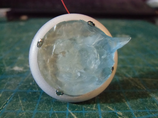
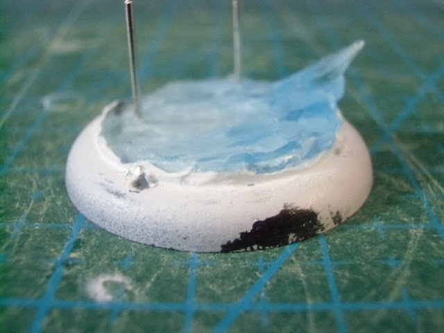
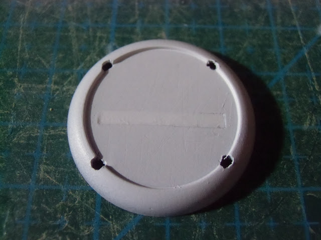
This is probably a good time to prime the base. We need a layer of white underneath the clear base topper to reflect the light upwards and illuminate the entire base topper. You probably don't need to worry about making the surface too uniform unless you are using a particularly clear base topper, but in that case you might want to paint something more complex on the surface as plain white might not look that good.


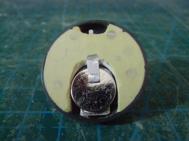
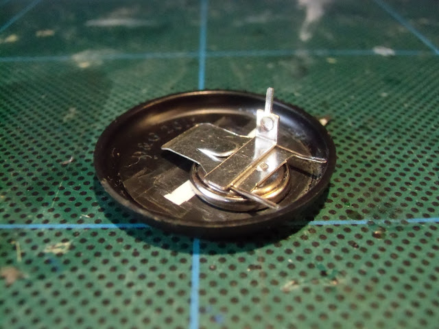
Now is probably a good time to mention that I use CR 1220 batteries. These 3V batteries are about 2mm thick and 12.5mm in diameter. I like to use a compass cutter to cut a hole the size of the battery from 2mm plasticard.


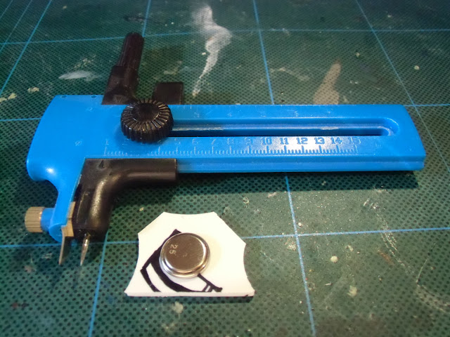
I'm sure there's much easier ways of doing this; you can use a drill with a circle cutter or something if you have one. If you do use a compass cutter, it's important to spin it backwards: you want to carve plastic away using the back of the blade, not to try to cut into the plastic with the edge.


It's a rather time-consuming process - it probably takes me at least ten minutes - so use a drill if you have one and don't mind the noise. Either way, make sure you attach the plasticard to a disposable surface before cutting (bluetack works for me, but if using a drill you might need something stronger).


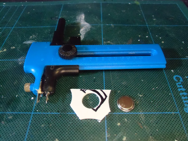
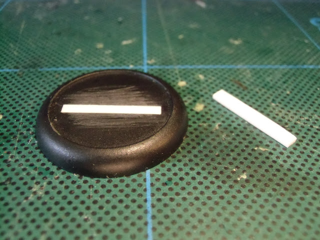
Now you want to cut the plasticard into a horse-shoe shape. I use clippers to do most of the work, and a hobby knife to clean it up.


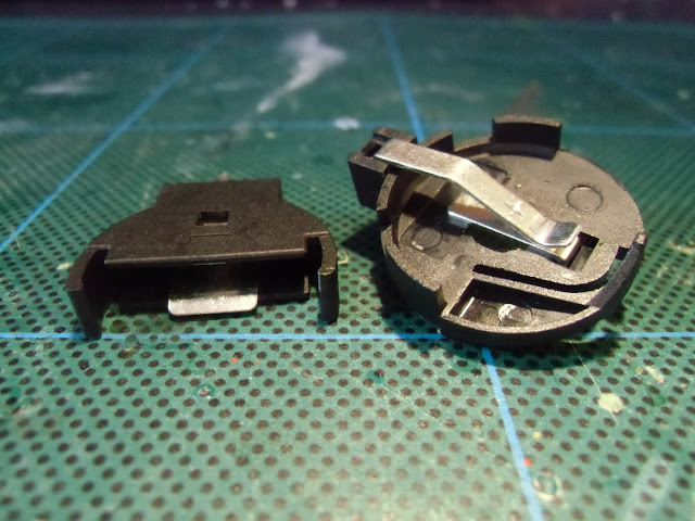
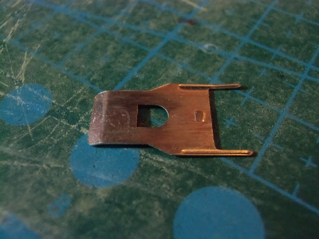
Now back to the metal bits. We want to flatten the large thin piece. I usually snap the middle bit off with a pair of pliers then file the whole thing flat with a metal file. You probably don't need to worry about the two prongs though as the battery will probably not be sitting that deep in. You can leave the lip as well as this can help to slide the battery out of the holder when it's all done.


Next, take the small L-shaped piece.


We want to snap off the small tab and introduce a second bend into the shorter arm. I do this using two pairs of needle-nosed pliers, but the fact is it's a very fiddly job. It can be hard to get the height right; it's probably better if it's a bit lower than higher. I often have to do this two or three times to get it right, so be patient and have spares ready to go.


It may be necessary to cut the long arm down a bit; if this piece will be attached from the side you won't need to do this, but if it's coming straight down you might. Sorry if that doesn't make much sense just yet, but hopefully it will soon.


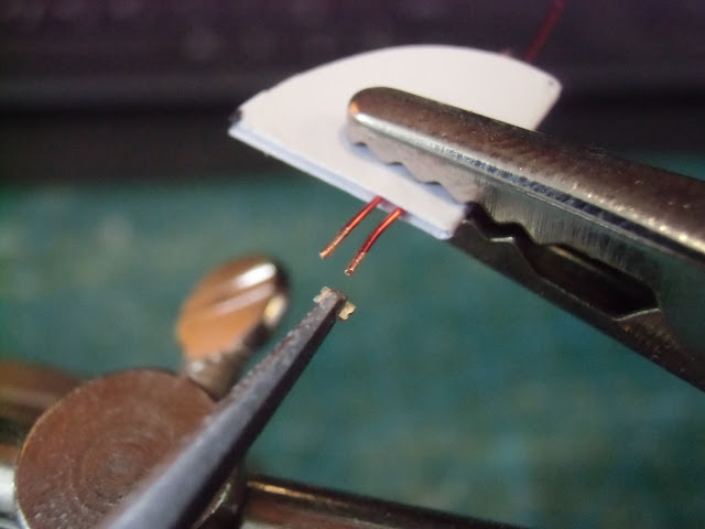
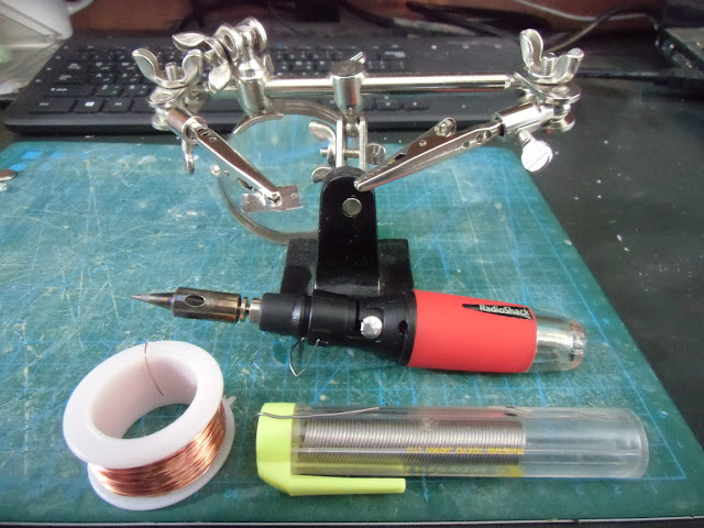
Now a quick word on soldering. I like to use a gas-powered soldering iron because I find that they heat up more quickly, you can control the temperature to some degree, and the shorter neck and lack of a cable sticking out the back makes it easier to do precise work. However, they do have jets of very hot air shooting out of the sides, so if you're not careful when soldering the hot air can melt the plastic of the base. I recommend holding the soldering iron as vertically as possible when soldering bits that area already stuck in place.

I got my soldering iron from Radio Shack several years ago, and I love it. I've found a little clamping stand (I think they go by the name "helping hands") to be invaluable for this kind of fine soldering work. As you can see I'm using laminated copper wire; I think the stuff I'm using is about 0.4mm diameter. Remember to scrape the lamination off the tips before soldering.


Of course it helps to do as much soldering as possible before the bits are stuck in place, as this reduces the chance of melting anything.


First the large piece is glued down. A rough surface can help this to stick well, but of course the surfaces are probably already rough from all the filing and sanding we've been doing.


Next we stick the plastic horse-shoe in place. Remember to carve it down as much as possible to leave room for other components, and to make sure to position it to hold the battery in exactly the right position. You will probably need to do some carving on the bottom for the electrode, otherwise it will not sit flat.


In this case I've soldered the switch in place before gluing it in. What you do here depends on the layout of your base of course. I just use small sliding switches from Ebay.


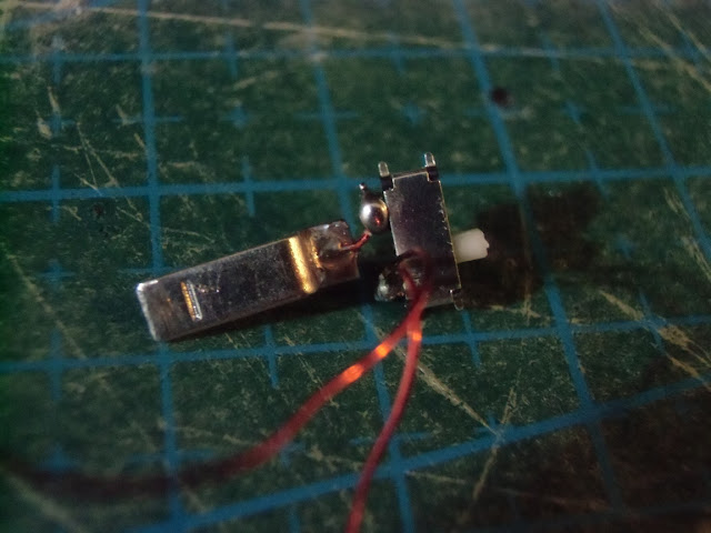
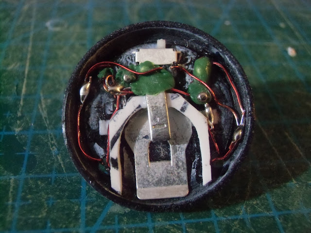
Now we glue the top electrode in place. This is what's going to hold the battery in, so try to attach it as securely as possible - I like to apply glue to the surrounding area then press some putty in place and give it a day to harden completely before I actually start sliding the battery in, to make sure the connection is strong enough to withstand the stress.

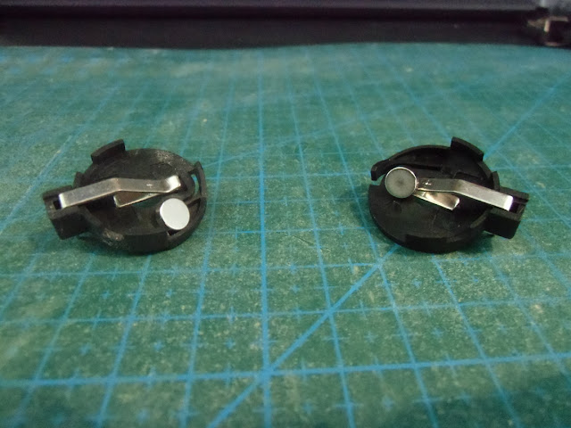
Notice that in this base I've glued the top electrode so it's pointing in the direction that the battery slides in and out; as mentioned above I had to shorten this one to make sure the battery could be taken out.


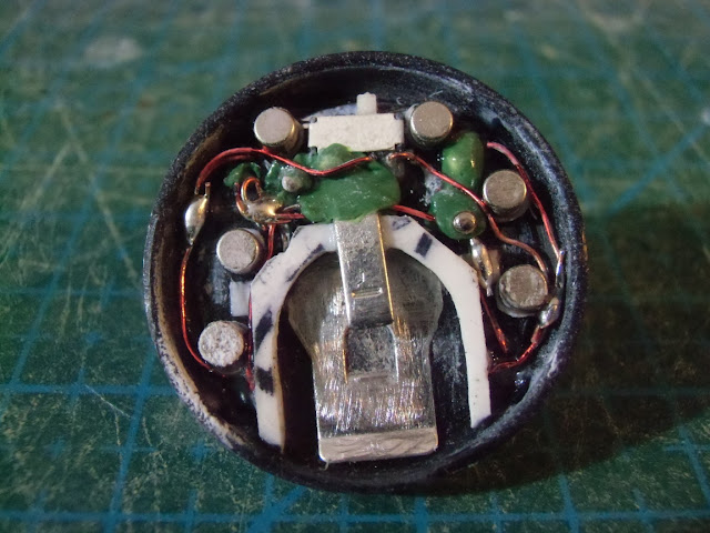
As you can see in this photo, it's also possible to have this piece pointing perpendicular to the direction that the battery slides in and out. This is often easier and you won't need to shorten it, but you do need to make sure to put it far enough from the edge of the base that the battery can be removed - the battery tilts as it slides out so if the electrode is too close to the edge of the base it will get in the way. The reason why I used the first method in this case was because that left me more room for the LEDs and wires around the rim.


Step 5: The Base Topper
Spoiler:
Obviously this whole step is only needed for light-up bases. The first thing to do is to stick the LEDs to the clear base topper.

I cut out four small indentations for the LEDs; you should be able to see them in the photo if you look carefully. This might not be needed depending on your base topper, but if you do cut them then make sure that they match the holes you drilled into the base.

This base is actually the "clear ice explosion" from Dark Age. It's made of clear resin; please remember to wear a breathing mask and work in a well ventilated area when cutting and especially sanding resin.


You can see the LED in place. This is a 0603 SMD blue LED; you can find these on Ebay, but I got mine from Lighthouse LEDs. These LEDs are tiny and very hard to use; you might be able to get away with using slightly larger LEDs such as 0805s, but the larger the LED the harder it will be to cover up later, so use smaller ones if you can.


I tried gluing the LEDs in place before soldering on the wires, but I eventually found it was easier to solder first then glue. For soldering LEDs I use a setup like this:


By using a pair of reverse tweezers to grip the LED in between the electrodes, it's not only possible to hold everything in place while soldering, it also helps prevent the solder from jumping across the tiny gap in the middle and short-circuiting the connection. As long as you don't touch the soldering iron directly to the tweezers they shouldn't get hot enough for the solder to stick to them. The paper is there to make sure the metal clamps don't scrape any of the insulation off the wires.

It's worth mentioning that these LEDs are very fragile, and it doesn't take much to rip the wire and the electrode clean off. It's probably worth reinforcing the back of the LED with a spot of thick gel glue or something and leaving it to dry for a bit before moving it. I destroyed a large number of LEDs before figuring out how to hold everything in place and handle them safely, and even now I often destroy two or three LEDs before managing to get one in place. So be patient, and buy a lot more LEDs than you actually plan on using.


It's best to orient everything the same way to avoid any chance of mixing up polarities. I tend to be very paranoid about getting polarities wrong, as mistakes are very hard to fix later, so I test everything at every stage. Once you've soldered wires to all the LEDs, you can glue them on to the base topper.


Once that's done you can glue the base topper down. Cyanoacrylates (standard super glues) can cause a "frosting" effect on nearby surfaces but at this stage we can still clean that off the resin if needed (and frosting along the bottom isn't a problem) so I just use regular super glue for this.


Step 6: Hooking Everything Up
Spoiler:
At this point you'll have a whole mess of wires underneath the base.


Carefully cut wires to the right length, scrape the insulation off the tips, and solder everything together in parallel. If you don't know what "in parallel" means you should probably find a good explanation online, but basically it's effectively the same as every LED being connected directly to the battery (as opposed to the LEDs being connected one after the other).

Typically blue, green and white LEDs have a working voltage of around 3V, so they can be connected to the battery directly. If you are using other colours you may need to wire in a resistor here, in which case I believe you would want to wire up the resistor to the battery and then all the LEDs directly to the resistor on one side and the battery on the other. So the resister is in series while the LEDs are in parallel... ugh, I don't really know how to explain this stuff, I guess find someone who understands electrical circuits if you need help. Also get them to figure out the best resistor. Or use an online resistor calculator, they aren't really too hard to figure out if you find one with a good explanation.

Again, I recommend checking the polarity of the wires at every step. Also I suggest always cutting wires a little longer than you think you need; you can always shorten them later, but it's awkward if they end up being too short. And again, be careful not to melt the plastic with the soldering iron. As you can see in the photo I use little bit of greenstuff for added insulation wherever wires would otherwise come into contact; I'm just a little paranoid about the insulation getting scratched and causing short circuits. You could probably just use tiny bits of electricians tape or something if you share my paranoia.


In this photo you can see several 3mm disc magnets that I've glued into place as well. Again, I try to make sure that they can't possibly cause any short circuits. You can also see the heads of a couple of pins that I'm using to attach the model.


I like to fill the base with milliput to protect and support everything. I do this in stages, using bluetack when needed to protect the switch and electrodes. Finally I flatten the bottom; I like to sweep the base across a sheet of sandpaper sitting on a flat surface in order to sand it completely flat and smooth, though the electrode will probably require extra work with a metal file to remove any excess height - it's best to do this with the battery in place otherwise you might find that the battery pushes the electrode outwards a little bit later, meaning the model won't sit flat. Again, do any filing and sanding in a well ventilated area and wear a breathing mask.


Here's a shot with the battery in place.


Step 7: Covering The LEDs
Spoiler:
So right now the base looks like this:


Not bad eh? But there's still one thing left to do: cover up the LEDs. Unfortunately this is where it all started to go wrong with this first attempt, but hopefully the next one will be better.

I decided that I needed to build up the sides of the base in order to hide the LEDs. The first thing I did was paint white brush-on primer along the side of the base topper where I expected to be covering it with greenstuff, as I didn't want the green to be visible through the clear resin. If you have a white putty you could probably skip this step.


Next I sculpted on the greenstuff, trying to get a smooth contour. After leaving it 24 hours to harden completely, I sanded it smooth and scraped off the excess primer (again, resin: ventilation, breathing mask).


As you can see, the greenstuff went too far up and the boundry is messy because of how I tried to mate it to the resin. Next time I'll try to have it end in a clean "shelf" rather than trying to blend it in.


Step 8: Paint
Spoiler:
After gluing the model on the top, I used a clear crackle medium to fill any recess that I didn't like the look of (basically the big depression in the center of the ice and some areas around the back of the model's coat, to make it easier to paint).

I covered the clear resin with a regular PVA (white school glue), then primed the whole model after the PVA was dry. You can also use bluetack or something, but the advantage of normal PVA is that it doesn't turn completely waterproof when dry (make sure you're not using a waterproof PVA). When trying to get rid of something like bluetack, it can stick in recess and it will be hard to get it off cleanly at the boundaries. But because the PVA can still be dissolved, you can slowly clean all the stubborn bits out with warm water and a soft brush without doing too much damage to the surrounding paint.

Seriously though, use warm water, it's much faster than cold. And be patient, the PVA can be slow to dissolve. As the PVA dissolves it will leave powdered primer and paint, which can get onto nearby surfaces. It should all be easy to clean off later though with a soft brush.


I like to leave the PVA in place until the painting is mostly done; less chance of getting paint on the resin. Of course this means there's a bit of repair work needed once the PVA is all removed. Alternately I guess you can take it off before painting, then remove any paint from the clear resin using, I dunno, a bit of brush cleaner or something. I might try that next time.

Once the model is painted, I like to coat the model and the base with gloss varnish. Once this is completely dry I will use washes to give the unlit base a little contrast. For ice bases I also drybrush a little white on top then coat everything with a matt varnish, but a gloss varnish might be more appropriate for a different type of surface - for example, I used a final gloss coat for my glowing swamp bases.


Step 9: And Finally
Spoiler:
If your LEDs aren't lighting up reliably, try bending the top electrode down a little bit so that it's applying more pressure to the battery. The act of sliding the battery in and out can bend the electrode outwards a little bit, so you might need to periodically re-apply the bend.

I like PP 30mm bases, but I've actually managed to build a powered 25mm GW base in the past. These are a little thinner, so I actually just cut a hole where the battery would go rather than trying to thin the plastic.

Of course that only works with a base topper, so you can't really do it without increasing the height of the base by at least a millimeter or two (technically you can build a powered PP base without any increase of height at all since you can just sculpt or paint a texture into the recess), but it's barely noticeable.

The photo below is of a GW 25mm base. You can see how thinly I had to slice the plastic horse-shoe here. The switch is pretty much soldered directly to the bottom electrode to save space. Also visible on the upper left side is the hole where the two wires pass through the base and into the model above.


Well, that's it. I guess all that's left to say is good luck.

--Lord of the Sentinels Eternal-- 
   
Made in gb
Hurr! Ogryn Bone 'Ead!


United Kingdom

The end result is gorgoeus, but good god man, that must take hours per base!
   
Made in om
Longtime Dakkanaut


Muscat, Oman

 Dannyrulx wrote:
The end result is gorgoeus, but good god man, that must take hours per base!
Thank you. The bases do take a long time to put together, which is one reason why I generally save them for "special" models like Warcasters.

--Lord of the Sentinels Eternal-- 
   
Made in de
Primus


Palmerston North

Very cool.

It looks like a lot of work, but worth it in the end.
   
 
Forum Index » Painting & Modeling Tutorials
Go to: