There was recently a tutorial on adding LEDs to vehicles, but it really didn't cover the details you need in order to do this. I've recently completed an
RT Rhino with LEDs and would have found a tutorial really useful, so I'm going to try to share my knowledge here. I've not done a tutorial before, so please ask if you have questions, or if I've missed anything out. Also, I didn't intend to do a tutorial when I was doing the work, but I was entering the DakkaDakka painting comp, so I have some photos but not quite what I'd have taken if I'd known I was doing a tutorial (
feel free to vote for me - or any of the other great entries - in the painting comp).
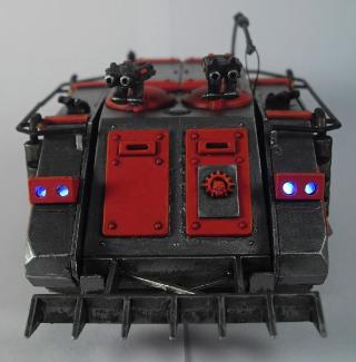
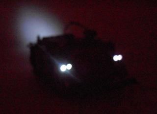
This is what we're working towards -
But before we do anything with need to understand LEDs and electricity. I'm not going to give a full physics GCSE course, but I'll cover the basics and give some links to good related tutorials.
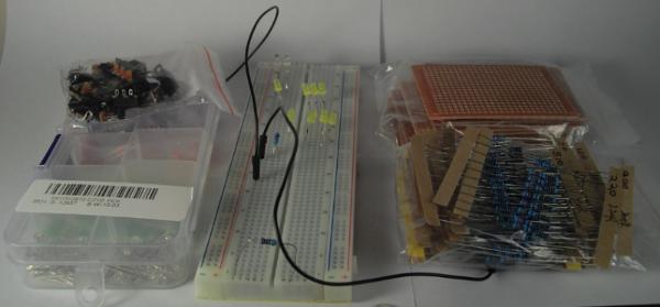
Create the circuit, complete with LEDs, resistors, battery etc on a breadboard to prove the circuit before you go near wiring anything into the vehicle. A breadboard is basically a testing board where you can easily plug in components such as LEDs and check the circuit. You can see the breadboard in the middle of this photo, along with some prototype boards (back right), resistors and switches.
You must include a resistor in the circuit, otherwise you'll just burn out LEDs.
Here is some good info on resistors and resistance. To work out what resistor you'll need you'll need to use Ohm's Law: V = I.R (where V = voltage, I = current in
amps, R = resistance in Ohms). The voltage is from whatever battery you're using. I used CR2032 coin cells which are 3V. The current is the current of the LED. This should be measured in milliamps, or mA and should be on the data sheet for the LED. The ones I used are 20mA. So this gives us 3 = 0.020 x R, or R = 3 / 0.020. So R = 150 Ohms.
This means the 3V battery will provide a current that's limited (due to the resistance of the resistor) to 20mA, so the LED won't get too much current and blow. It actually makes sense to use a slightly higher resistance, maybe 180 Ohms. It might depend on what resistors you have available and what the values of your LEDs and batteries are, but always go over on the resistor, not under. You can also combine resistors, so if you find you need a resistance of 165 Ohms, you can use a 150 Ohm resistor and a 20 Ohm resistor in serial to give 170 Ohms. See the link above to SparkFun for more details on resistors, values and combining them.
Now we need to check the forward voltage drop of the LED. Again, this can be found on the LED's data sheet. The ones I used had a voltage drop of 1.8-2.2V. This means that the voltage coming out of the LED will be 1.8-2.2V less than what went in. So with a 3V battery powering an LED (+ side of battery connected to - side of LED), the voltage coming out of the + side of the LED will be about 1.2V. If you then have a second LED there's not enough power to light it. Try this on a breadboard and you'll probably see both LEDs lit very dimly. Add a third and they won't light up at all. I have 8 LEDs in my Rhino, so we need another solution - I don't want to have to use 5+ batteries!.
See SparkFun for more useful info on LEDs. Note: LEDs' legs are different lengths. The long one is + and the shorter one -. If you get an LED the wrong way round it won't work, but it won't damage the LED, so if your circuit isn't working, just flip the LED around to see if that's the problem.
One last thing to check, which shouldn't be a problem if you're using an appropriate battery, is the power going through the resistor. If there's too much power to the resistor you'll burn it out. To work out the power (Watts) use P = V.V / R. So with our values that's 3x3 / 150 = 0.06W. My resistors are limited to 0.25W, so are easily up to the task.
What I described above - having a battery wired to an LED (positive to negative), then that LED wired to another one (again positive to negative) etc - is a 'serial' circuit. You have one component after another in a big loop. However, if you wire the LEDs in parallel, the forward voltage drop isn't cumulative, so you can power all 8 LEDs from a single battery (I assume this will affect battery life, but I'm afraid I don't know how to calculate that - can anyone help?). In a parallel circuit you effectively run a single wire from the positive side of the battery to all the negative legs of the LEDs. Then a single wire from all the positive legs, back to the battery (remember to put the resistor between the battery and LEDs on one of those wires too - it doesn't matter which side).
More info on serial and parallel circuits.
So on your breadboard you should now have a battery wired up (best to use a holder for the type of battery you're using - it's easier to wire up and you'll need one in your Rhino or whatever vehicle you're lighting up), a resistor and one or more LEDs in parallel. Rather than pulling the battery out to turn the lights off, you just want a switch. You should be able to just drop an on/off switch into the circuit, maybe just after/before the battery. This will allow you to just flick a switch to turn the lights on and off.
Okay, that's the physics lesson taken care of, now you need to fit it all into a tank.
My LEDs are 3mm, so I drilled holes of about 2mm everywhere I wanted a light. I didn't want the LEDs sticking right through, but rather be sunken. Obviously, if you want them coming right through you'll need a 3mm hole. I then widened the holes on the inside to allow the LED to sit in a bit deeper. It all depends where you're putting them and how sunken you want them to be. I used superglue to fix the LEDs in place. I've not had a problem yet doing that, and as long as you're careful and don't use too much glue, you shouldn't cloud the LED lens.
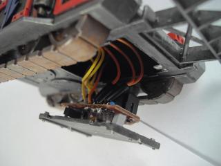
Next up is the wiring. I soldered a wire to each leg of each LED, so 16 wires in total. Because all my lights are in pairs, I actually pulled the legs on each pair of LEDs together, so I could solder a single wire to each pair, so I ended up with 4 positive wires and 4 negative wires. I used one colour for all the positive legs and another colour for all the negative legs. I fed all the wires through the hatch on the bottom of the Rhino. It depends how you want to access the battery and switch as to where you'll need to run the wires. You'll probably also need to cut out some bits of plastic on the inside to be able to run all the wires through. It's not a very clear picture, but this shows the wires coming from the LEDs in the back of the Rhino -
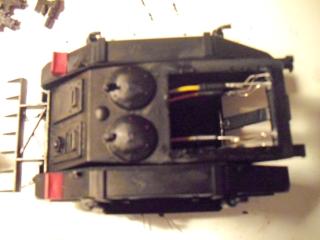
And then this one shows some of the wires coming out of the bottom hatch -
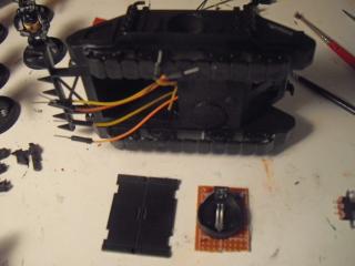
In the foreground of the above you can also see a small piece of prototype board with a battery holder. Prototype board is circuit board with loads of holes in to allow you to wire up the components however you like. You'll then need to solder them in place and to connect them together. I made the board small enough to fit on the back of the hatch, and added the battery holder, resistor and switch to it. All the positive wires from the LEDs were soldered to one spot on the board and all the negative wires to another. These could then be soldered to the respective parts of the circuit.
To make everything fit (and it's pretty tight), I put all the components on one side of the board, and glued the board to the hatch with small pieces of sprue. This gave a gap between board and hatch to fit the switch. Finally, the hatch was magnetised. So I can pop the hatch off and get relatively easy access to the switch, and if I need to I can pull it a little further out to swap out the battery. Make sure you have enough length on the wires to allow you to do that. I made a few of my wires a little short, so it's not as easy as it should be!
So, I hope that all helps you to understand what's needed for create a circuit for your LEDs. You can use this to light up anything really - tanks, terrain, stompas - whatever takes your fancy. Make sure you have sufficient resistance (you don't want to have to swap out burnt out LEDs) and easy access to the battery and switch.
Thanks to
SparkFun, which is where I got all my info from when doing this. Their various tutorials on resistors, LEDs etc are really useful, and there's loads of other links to Ohm's Law, serial and parallel circuits and other useful info.
As for sourcing components, this is what I bought (all from eBay, mostly from China):
-
Breadboard £3.15
-
100x 3mm LEDs £1
-
200x 3mm ultra bright LEDs £2.11
-
300x mixed resistors £1.03
-
10 x prototype boards £1.14
-
20 x on/off slide switches £1.99
-
10x battery holders £0.55
-
5x CR2032 3V batteries £0.93


 Dark Angels/Deathwing - just getting started!
 Space Marines -
 Eldar - Biel Tan 2000pts

 - 2500
 - 1500? 2000?
 - 550
- 550 
