So I got some requests a bit over a week ago to throw up a tutorial on how I made my Vulture out of a Valkyrie kit. This is my first tutorial on Dakka, but I apologizes in advance for the MS Paint pictures/diagrams you are about to see. Unfortunately I didn't take too many pictures during assembly, so I'm making up for it with my mad MS Paint skills. And by mad, I mean really awful. Well, enough of the chit chat. Here's what you need/do:
Materials:
2” x 1.5” PVC Coupling (This is the turbofan housing)
1” PVC Adaptor (Slip x Thread) i.e. it has a smooth end and a threaded end.
1” x 5’ S40 PVC pipe plain (basically any PVC pipe that will fit inside your smooth 1” Adaptor end.)
1 or 2 sheets of plasticard
Wooden dowel (fairly think. At least thick enough to cut a grove in it without endangering its structural integrity)
Reflecting funnel from flashlight that will fit in Coupling (I got mine from a toy light saber)
Scissors, Ruler, pencil, Xacto knife (the usual)
Dremel Tool (with: grinding disks, sanding attachments [large and small], and some sort of cutting/digging attachment)
Saw (I used a band saw, but a hand saw should work albeit take longer)
Sand paper
Greenstuff (mostly to fill in gaps later on)
Valkyrie Kit
Preparation:
SAND EVERYTHING! It was my assumption that PVC was a fickle material to work with so I sanded every part going into this so that Super Glue and paint would stick, allowing me to build the model in the first place.
Proceedure:
Step 1: Assemble cockpit as usual, but leave out windows until last. Cockpit hull has small slant where it attaches to the original transport area of the Valk. You need to cut this (red dotted line) so that it leaves a 45⁰ angle like so:
Do this so the PVC Coupling will fit flush with the cockpit later. Also enclose the rear of the cockpit with some plasticard as shown in the picture above (blue line).
Step 2:
Measure and cut out 1cm thick strips of plasticard. Then cut out of the strips as many 1inch lengths you can get. These are your fan blades. Of course 1 inch is extremely long, but they will be cut down later once they are attached to the funnel. The length gives you some wiggle room when assembling the turbine shaft.
I didn’t do this on mine, but realized it would help later, but you should cut some sort of curved groove in the end that will sit/fit into the dowel to be glued. Gives more surface area of blade to be glued down on the curved surface of the dowel.
As for the wooden dowel, cut it to length, 5 inches should work. Now, cut a groove all the way around the dowel roughly 1 inch from one of the dowel ends. The groove should be deep enough to fit the blade ends in, but not deep enough to wreck the dowel (probably 2-3
mm). The groove should be about 0.6-1cm wide (same width as blades). This is so that you can angle the blades in when gluing them down so that they can overlap more easily and create a more realistic intake look.
This part isn’t too bad, b/c if you mess up there is more than likely enough dowel and plasticard to try again many times over. Time consuming, but no pressure.
Note: A lathe would be perfect for cutting grooves, but unfortunately I didn’t have access to one and the time, and I’m assuming most of those interested in this build don’t have access to one. So I carefully used the grinding disks and my Dremel to slowly create one.
CAUTION! Whenever you used a Dremel, especially with the thin grinding disks I’m speaking of it is of utmost importance you wear goggles! Many a time has a grinding disk exploded on me from the friction imposed on it. The last thing you want is one of those fragments in your eye.
Step 3:
Take your reflecting funnel and make certain it fits into the large end of your coupling and rests easily on the threaded end of your 1” Adaptor. You will need to make sure your dowel fits in the hole of the reflecting funnel. If it doesn’t sand out the hole until it does fit. Also, sand the back of the reflecting funnel so that it can be later glued to the PVC Adaptor inside the Coupling.
Step 4:
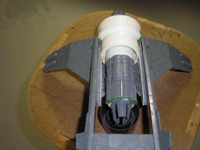
Glue in the adaptor into to the rear of the Coupling so that the threaded end is sticking out into the larger hood of the Coupling and the smooth end is sticking out the back. I used Gorilla glue to glue this part in, but PVC pipe glue should work too. You can then fit your other PVC pipe piece (3-5 inches long, depends on how long you want your engine to look) into the smooth end of the adaptor now if you wish. You shouldn’t have to glue this, b/c PVC pipe tends to have an already snug fit, but if you feel the need go for it.
Once that is done, Glue the dowel into your reflecting funnel so that the blades rest against the funnel’s sides. Now you will need to trim down the Plasticard blades to fit the Funnel/Dowel assembly into the Coupling. This shouldn’t take too long, and if you mess up and cut a blade to short you can extend it again with some greenstuff.
After that is all done, glue the Funnel/Dowel assembly into the Coupling on the threaded end of the Adaptor. Once everything is dry, cut the end of the wooden dowel sticking out of the front so that it is flush with the coupling edges.
Step 5:
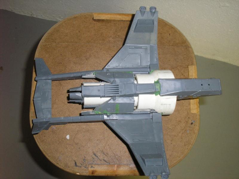
Super Glue the cockpit into place like so:
You should be able to glue the bottom of the Coupling to the cockpit and the end of the wooden dowel to the Plasticard you placed on it earlier. If not, add more Plasticard till it will touch and glue.
Step 6:
Cut this piece along the red lines like so:
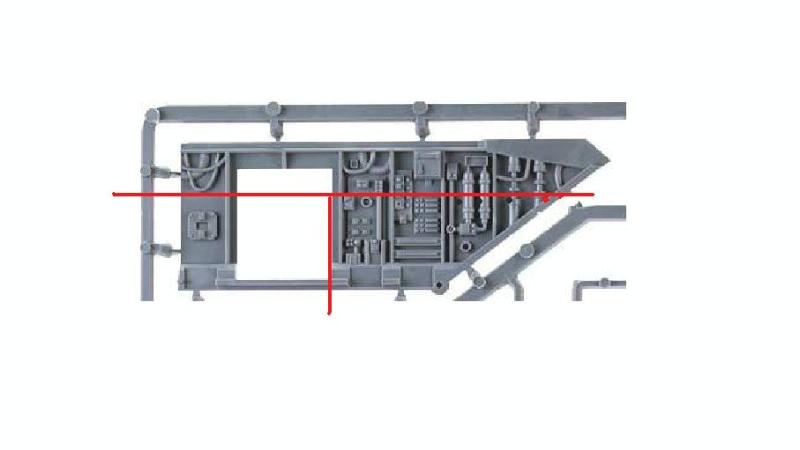
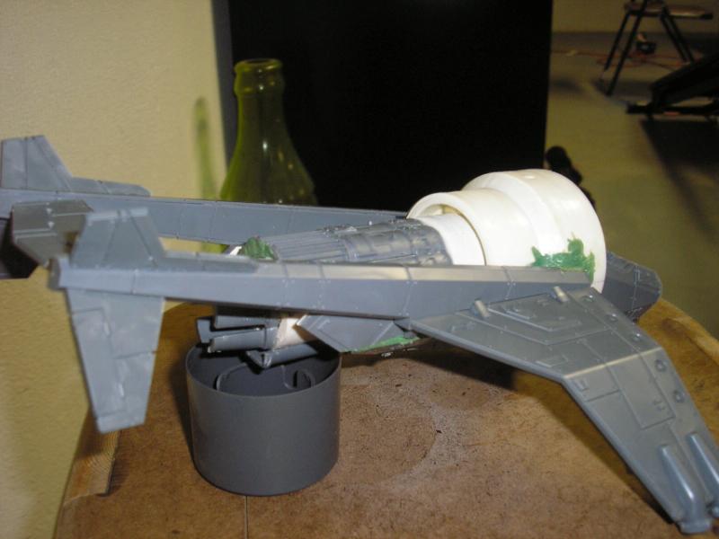
Or at least cut the top so that you have the part that attaches the tail booms to the original transport hull. This is going to act the same way, however instead of attaching to the transport bay it will attach the booms to your engine. Save the bottom Right portion as well. This will be used to make sturdy this structure after the wing booms are assembled and attached to the turbine like so:
Step 7:
Probably the most difficult part of this build. You will need the Dremel for this and the grinding discs, sanding drums, and drill/gouging bit. What you need to do is cut into the sides of the coupling so that you can fit the top piece you cut out in Step 6 onto the sides of the turbine so that it lays flat and looks a part of the entire build. If you can figure out any way around this step I advise it, because it is difficult to get both sides to match up. I suppose a ruler and pencil help but on such a curved surface it is difficult to determine the midline of the engine.
So what you do is cut a square the size of your boom assembly into your coupling halfway into the large end and ending where it tapers off into the smaller end. The smaller end will have to be sanded flat so that it rests flush with the boom assembly. I hope these pictures help in describing this to you:
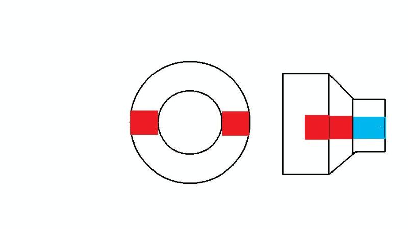
The red squares indicate where you need to cut and the blue indicates where you need to simply sand flat a bit.
Once you have the general hole/square cut out you will need to refine it with the sanding drums and such. Constantly check your work by seeing if the boom fits yet. Once it fits it should be good. Now you want the TOP part you cut out in STEP 6 to lie parallel with the engine. This will then allow the wing/tail booms to angle up as they do on the original Valk and Vulture. This is basically using the original design of the Valk to your advantage. That is why we cut out the piece in STEP 6.
Fill in any gaps with greenstuff.
Step 8:
Assemble the rest of the tail as normal and go to the belly of the model. From here you will used that weird piece from the original kit that sits along the middle of the transport/cargo bay between the 2 engines (the slanty one). You will cut this to fit along the belly like so:
This is fairly simple as you just need to make a few measurements and hold it up to the model a few times to get an idea of where you need to cut and how deep.
Once this is done use the other BOTTOM RIGHT piece you cut out in Step 6 to shore up the wing/tail boom assembly. You’ll probably need to sand /cut it till it fits. But this should give you the idea on how and where it goes:
Step 9:
Detail it however you like. I put landing skids on mine with some bits and slicing the rear door of the Valk in half, but you don’t have to. Say they’re retracted or something if you like.
Now go to the Cockpit again and take the piece that sits behind the top seat that allows the top glass piece to fit in on the original kit. It should have the 2 little turbo fans on it. You may need to sand it down/cut it so that it fits this particular build. Keep checking to make sure your cockpit glass fits in well with it. Once that is done, enclose the sides of the cockpit to the turbofan blades with plasticard, bits, and greenstuff. The general idea is to get something like this:
That will enclose the wooden dowel and hide any nasty looking glue job (like mine

) on the blades there may be.
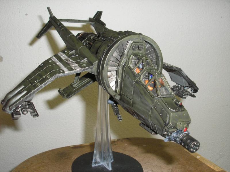
Step 10:
Prime / paint however you like, and finish with the glass on the cockpit.
And there you have it. 10 Steps to converting a Valk to a Vulture.
I hope my MS paint skills were helpful enough as well as my explanation of the procedure.
I’ll try and answer any questions as best I can, but this is pretty much the best way I can describe what I’ve done.


 3000+
3000+
 2000+
2000+
 1500+
1500+ 


 Kreig - 2850 pts
 Skaven - 3450 pts
 Orks - 1950 (pro painted)


 2500pts Ultramarines
  Starting Dark Angels
  Starting Tau
  FOR THE EMPEROR!
  4250 points of Blood Angels goodness, sweet and silky
  1000 points of Teil-Shan (my own scheme) Eldar Craftworld in progress

 's in my life!