Forum adverts like this one are shown to any user who is not logged in. Join us by filling out a tiny 3 field form and you will get your own, free, dakka user account which gives a good range of benefits to you:
No adverts like this in the forums anymore.
Times and dates in your local timezone.
Full tracking of what you have read so you can skip to your first unread post, easily see what has changed since you last logged in, and easily see what is new at a glance.
Email notifications for threads you want to watch closely.
Being a part of the oldest wargaming community on the net.
If you are already a member then feel free to login now.
This is a copy of my Wordpress - Go to http://www.gingerwerewolf.co.uk for the full thing and more Pictures of the Finished Vehicles
Ive wanted to add lights to my models for ages, and recently I got my arse in gear and worked out how to do it, and actually done it (I’m a great Procrastinator)
I decided to look it up on the internet and in loads of 40k forums there are people who have done this. There is some ace inspiration out there, and some great stuff has already been done in the field of Model Lighting. Heck just google “Warhammer 40,000 lighting” and you’ll find a plethora of sites.
Now making models have lights is an easy enough project but it needed to be worked out a bit. I had to make some decisions:
How many and how bright would I want the lights to be?
Coloured Lights?
What I was going to use as a battery, and where to put it?
What was I going to do about switching mechanisms?
How was I going to hide the parts?
Where would I get the parts from?
Since Im in the UKwww.maplin.co.uk was my first port of call for lots of this stuff. I bought a lot of their starter sets, as they are usually cheaper if you have nothing!
List of what you’ll need:
<strong>Tools</strong>
Soldering Iron – about 10w should do it. If you get a 40w one like I did initially, you’ll end up nearly melting plastic of the models, as a lot of soldering is done in-place.
Wire Cutter and a knife to help strip the wire. Or an actual wire stripper.
A heat proof mat to solder stuff on.
Drill with various Bit sizes (A Dremel is SO useful! Maplin sell them and cheaper versions as well)
A 3mm drill bit is essential, and the GW hand Drill will hold it if you can’t afford the Dremel.
<strong>Consumables</strong>
Masking tape – To hold stuff in place while soldering (note no plastic tape which melts. NB masking tape will burn though be careful!)
Electricians Tape – To cover up bare wires once done.
Solder – Goes without saying but its surprisingly expensive.
Wire
Resistors
LEDs
Switches
Batteries
Battery Holders
Patience and Practice
Details on how I chose the Consumables:
Wire – for this I found that there are two types of wire, Single Core and Multicore. Single Core is great if you want the bend the wire to shape and have it keep its shape, multi core is great if you want a little bit of flex to it so those moving parts can stay moving.
Resistors – They are appropriate to the task at hand / how many LEDs and what you use as a power source. More later on that.
LEDs – I chose colour, size and brightness depending upon what I wanted to light up. Maplin sell flashing LEDs for beacons, ultra bright ones for headlights, and practically every colour under the sun! Most of the LEDs I chose were 3mm which were small enough to embed into the models, but big enough to be bright.
Switches - This is very much personal preference, I went for a Single Pole Sub-miniature switch just because its small and easily hidden on Tanks and the like.
Batteries – Well this depends upon how many lights you want to light up.
The 3V Lithium Coin Batteries are perfect for miniatures / Objective Markers but only really light up one LED for any length of time.
The 12v 23A N size battery (used in Car remote controls) are perfect for tanks as they are smaller than a AA size but with 4 times the power.
9V PP3 work well too. They are also cheap and readily available and fit into the back of a Rhino / Chimera easily.
Battery Holders – Depend upon which Battery you go for.
Patience and Practice – Kinda goes without saying!
Instructions time:
First of all you need to know how to wire up your LEDs and not burn them out or other things. So heres some important things you’ll need to know.
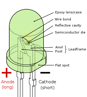
LEDs have a way round. That’s what the D is for Diode. In all cases LEDs come with a short wire and a long one. Circular LEDs have a flat edge to one side too. The Below image is perfect for this:
(Thanks Wikipedia)
In Fact it probably worth reading through the Wiki Entry for LEDs at this point to get an idea of what they do and are for.
LEDs have a Forward Voltage and a Forward Current and depending upon what Battery you use to power em, you may need a resistor to stop them from burning out. When you buy LEDs you should get all that info written down as you’ll need it.
Now if you are a hard core electrician you will then be able to use your skills to work out how many LEDs, and what “Ohm-age” resistor you’ll need.
I swear this place is great! Allows you to work out exactly what you’ll need to for your circuit and even give you the colour coding of the resistors you’ll need. I can’t thank the website owner enough!
So once you know your circuit that you want to create, you can start with getting the stuff together.
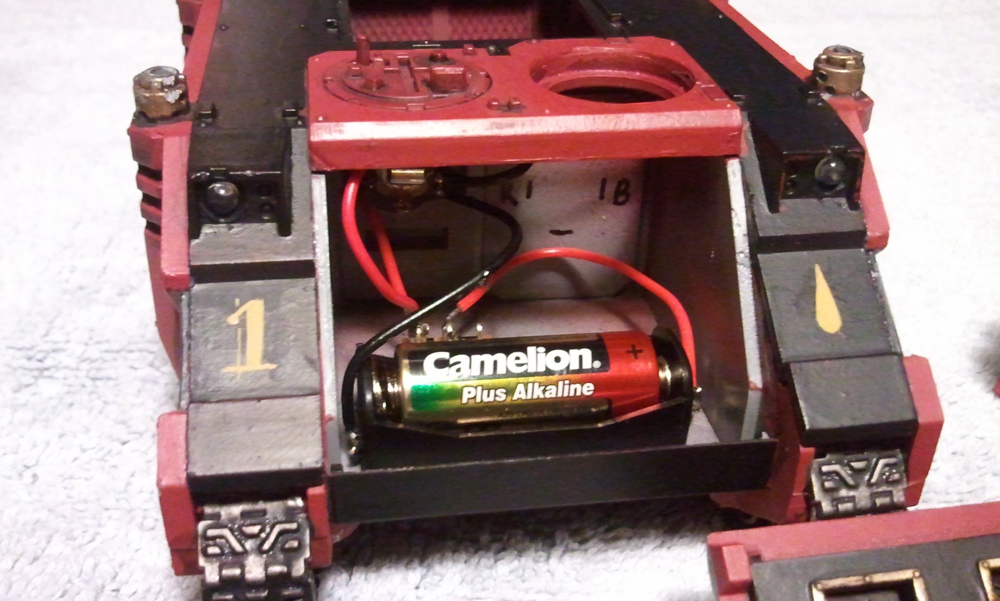
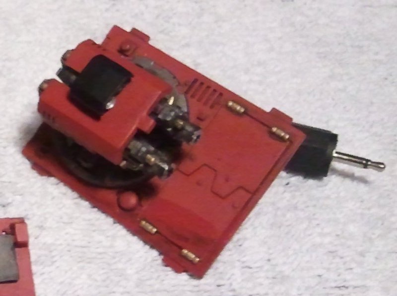
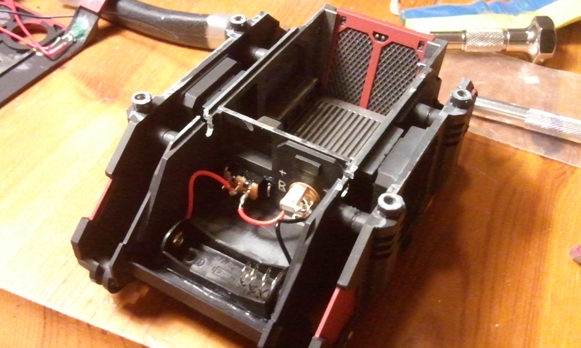
Im making a Razorback from the previous post, and here’s the inside of it:
Note that as I dont always want to connect the Razorback turret with its little light, so I use a 2.5mm Mono Jack to allow it to be disconnected (for when I want to use the Razorback as a Rhino)
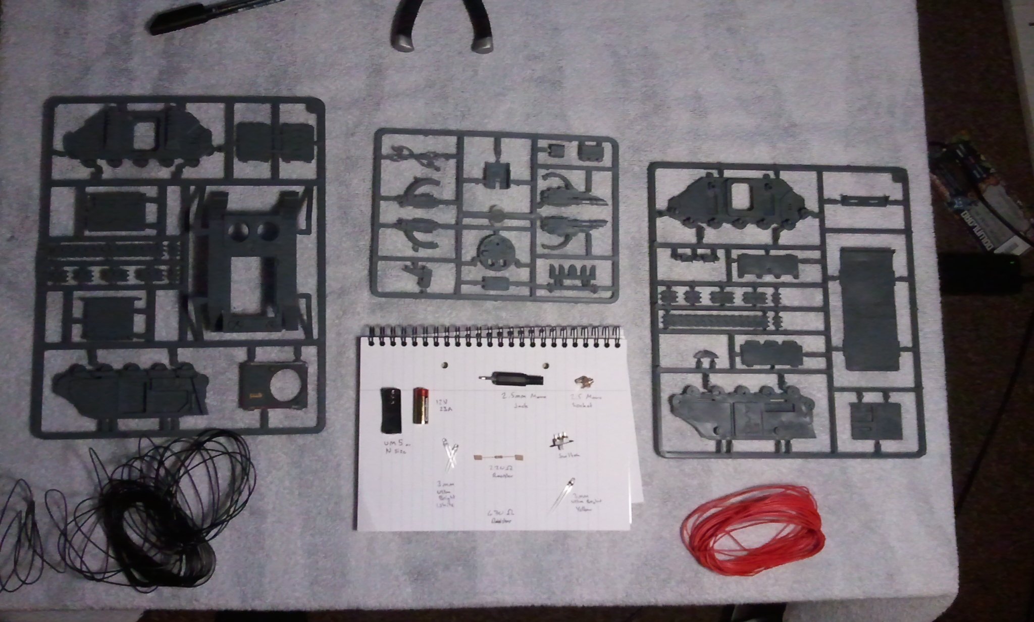
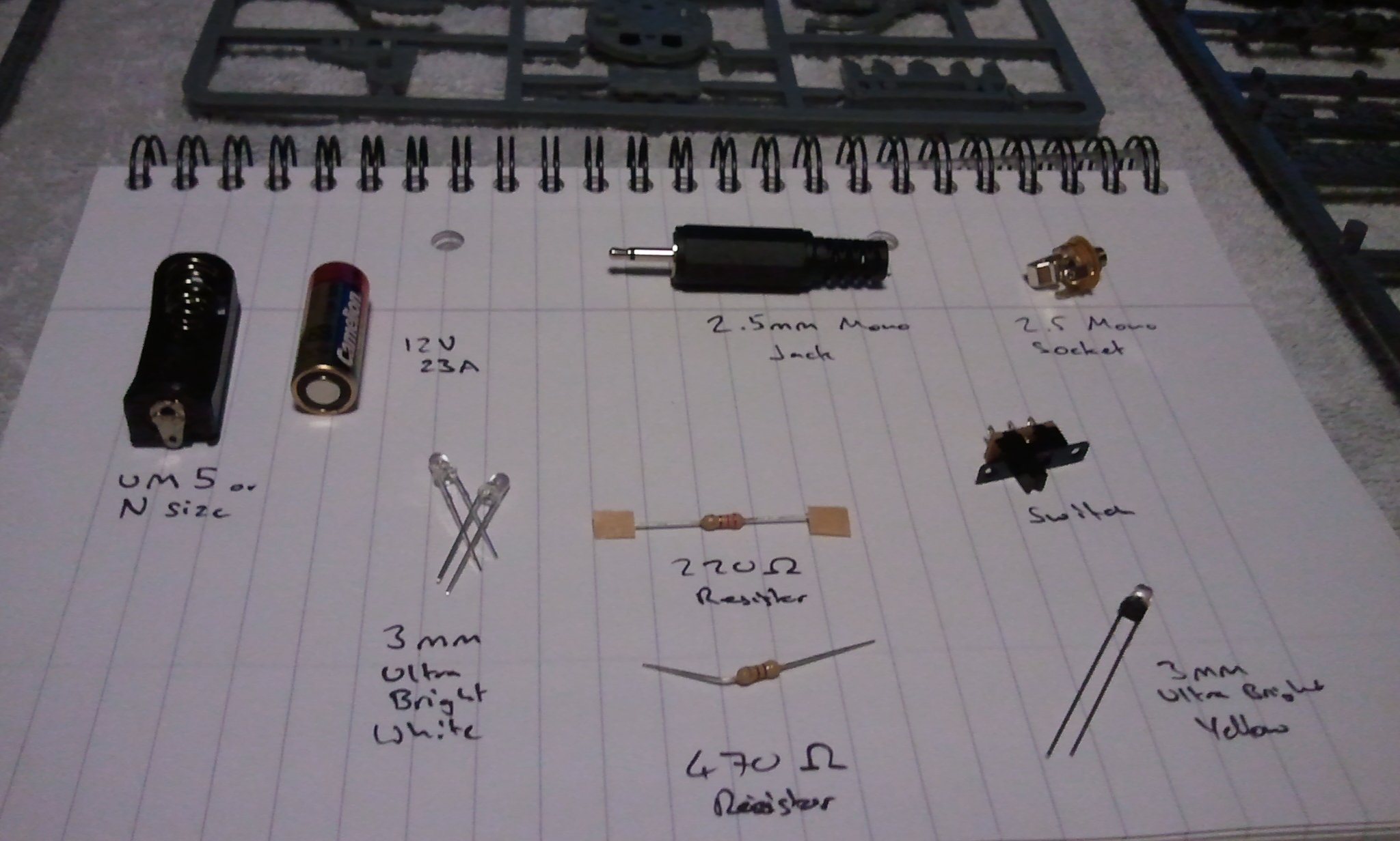
Here’s the components I used:
And a closeup of the electronics
List
1 Razorback Plastic Kit from GW or your Local Hobby Centre.
1 UM5 or N size Battery Holder
1 12V 23A Battery, N Size
2 x 3mm Ultrabright White LEDs
1 x 3mm Ultrabright Yellow or Red LED
1 x 220 Ω Resistor
1 x 470 Ω Resistor
1 x Switch
1 x 2.5mm Mono Jack
1 x 2.5mm Mono Socket
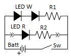
And below is the circuit Diagram
LED W = White LEDs
LED R = Yellow or Red LEDs
R1 = 220 Ω Resistor
R2 = 470 Ω Resistor
Bat = Battery
Sw = Switch
The Arrow things represent the 2.5mm Mono Jack connector
<strong>So onto the building of the thing!</strong>
Right in some cases its best if you can paint some parts on the sprue. In some cases its good if you can do some modelling without building the parts, and at other times you have to build them, and paint them before you can even get near em!
Word to the wise, it is very difficult / impossible to put lights into an already built tank. No I cannot convert your Golden Daemon Prize winning tank into one with lights. Its easier if you do it as you go along.
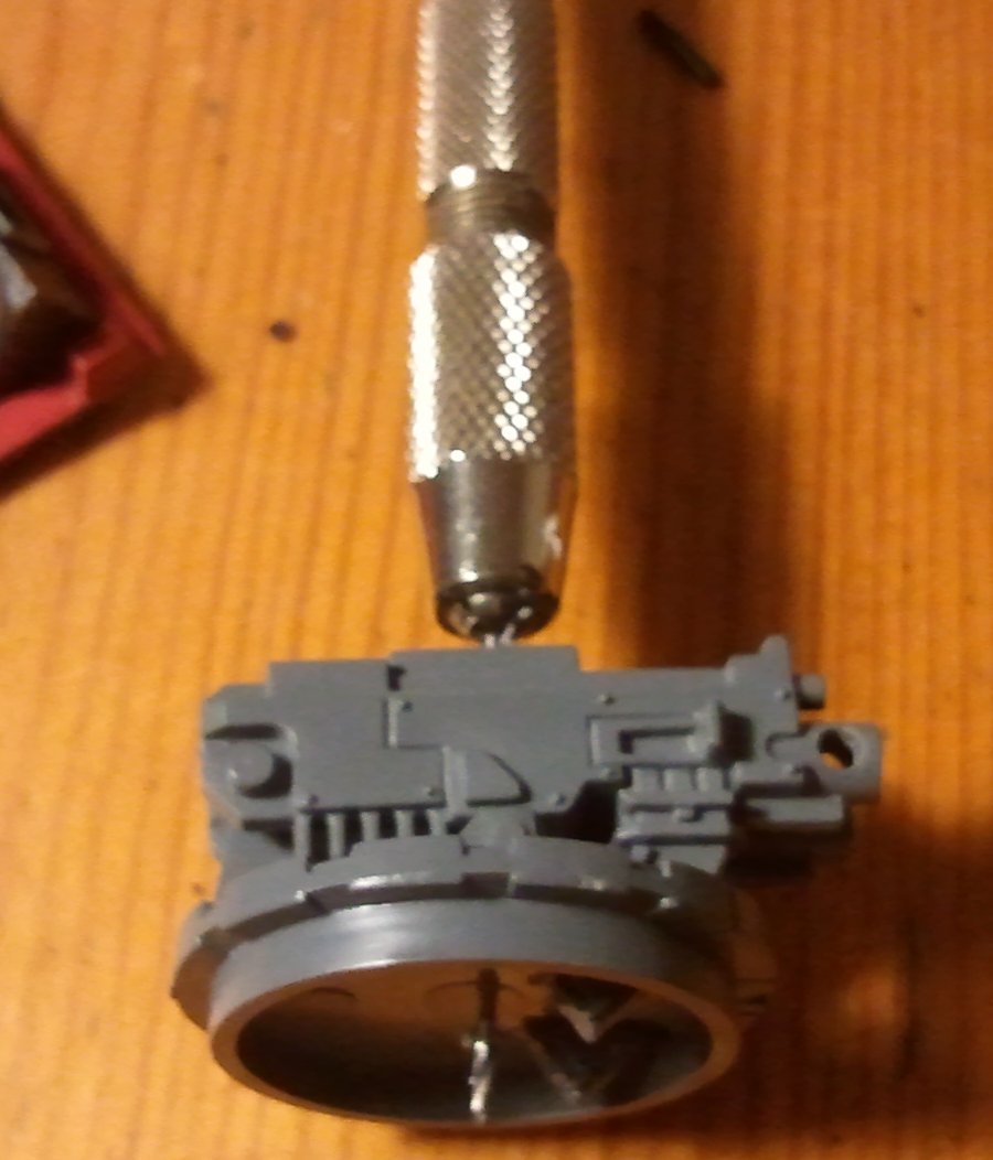
So first of all an easy part, the Turret. This will get you started on a bit of soldering and a bit of drilling. Ease you in!
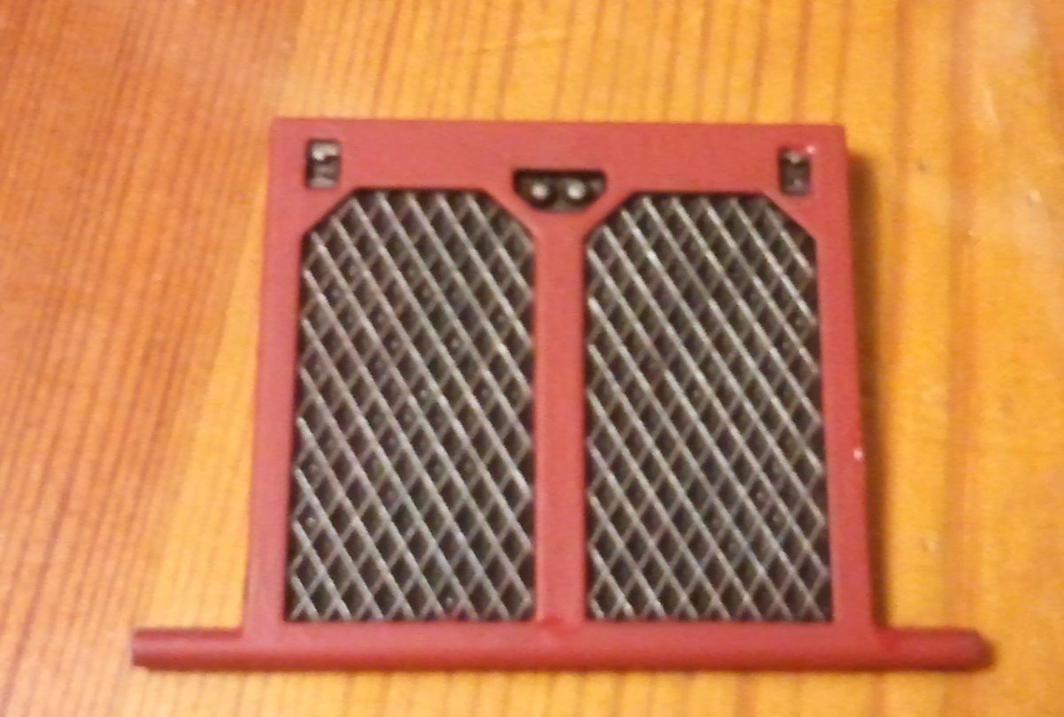
Build the Turret from the Razorback kit, gluing everything in place, but do not glue on the cover:
Clip off the excess ammo feeds so that it can sit flat on the table top, as unfortunately it is going to loose its ability to track up and down.
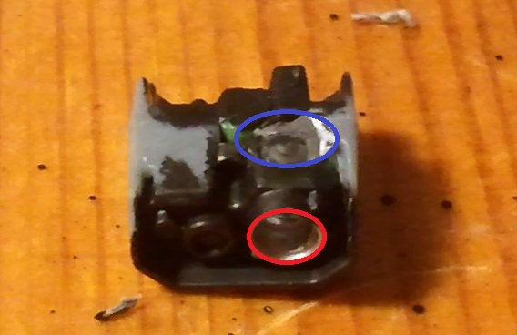
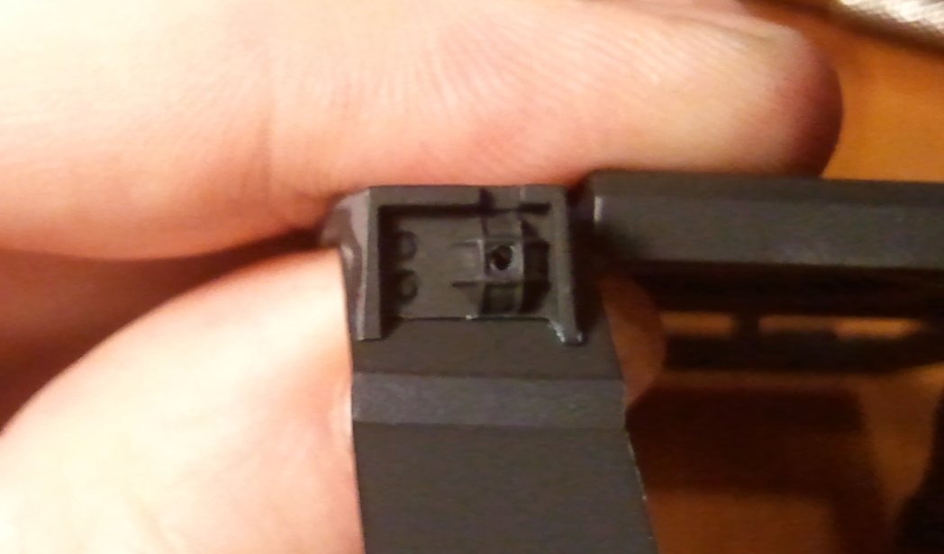
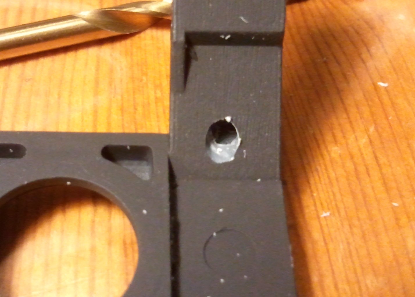
Get the Sensor array off the sprue and carefully drill 2 holes in it.
The first hole should be through the lens at the front, the second should me a 3mm hole in the bottom leading to the hole. See below for Profile and pic
Hope this makes sense as the blue hole has to connect the Red hole. Ive marked them up on the Pic
At this point you need to spray it black and then using Silver Paint, coat the inside (to help reflect light, it does make a difference)
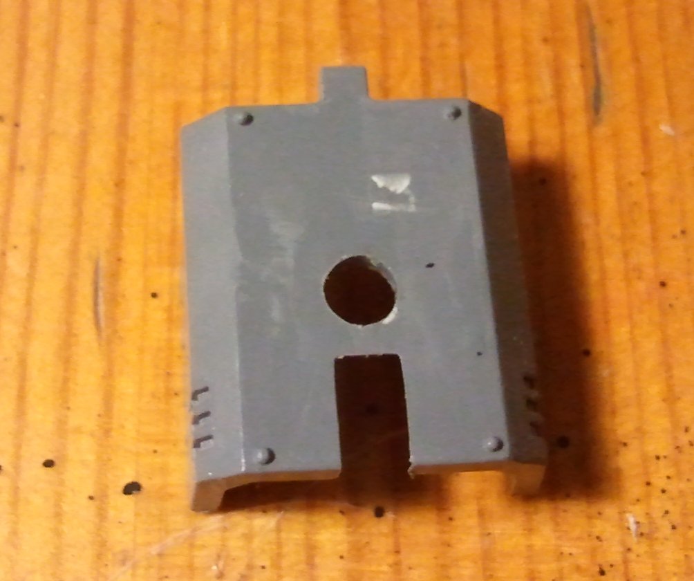
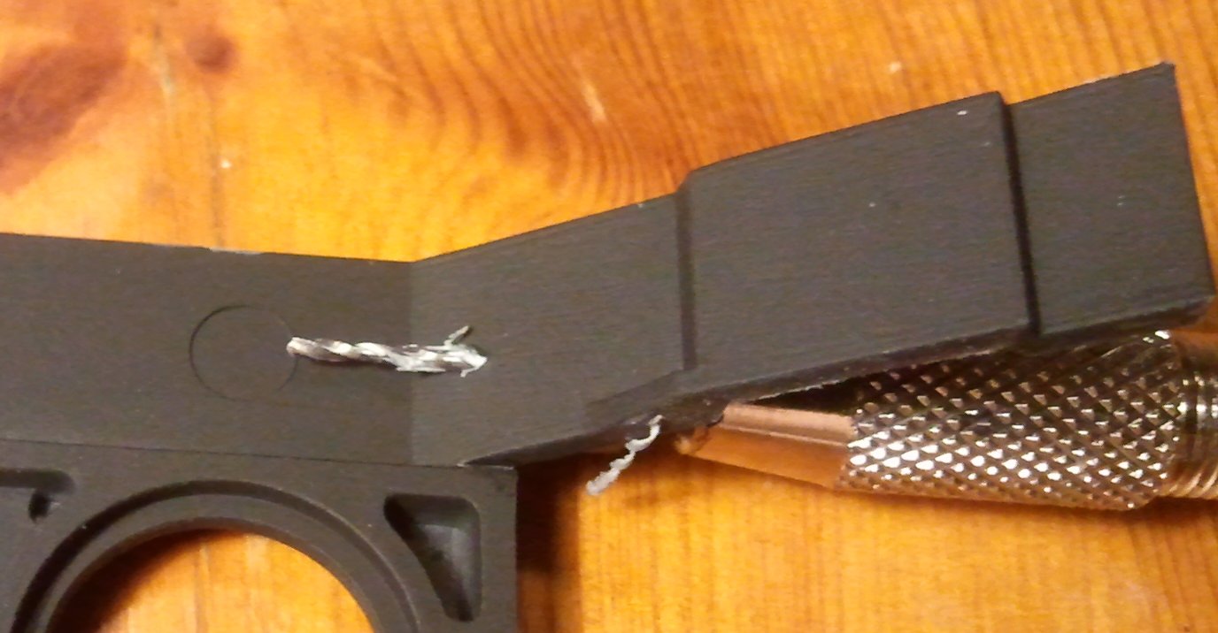
Then moving onto the cover, you need to drill a 4mm hole (or a 3mm hole that you use a File to make wider) in the centre towards the rear. Then file off / snip of the Protrusion you originally glued the Sensor array to. See pic below.
Then place without glueing the Cover onto the gun and get your small 0.5mm GW Pin Vice. Using the Larger holes as a guide, mark two points as below
The distance between the two red holes that you are about to drill is decided by the distance that the anode and cathode on the LED are from each other. Measure them, but on a 3mm LED they'll be about 2mm apart.
Set the drill bit at its maximum length. You are going to drill 2 holes through it from top to bottom. It doesn’t matter if they end up not going through everything, as this will be hidden in the workings of the Turret.
Then go off and undercoat and Paint the Turret. You want to paint it at this stage to avoid getting paint on the LED.
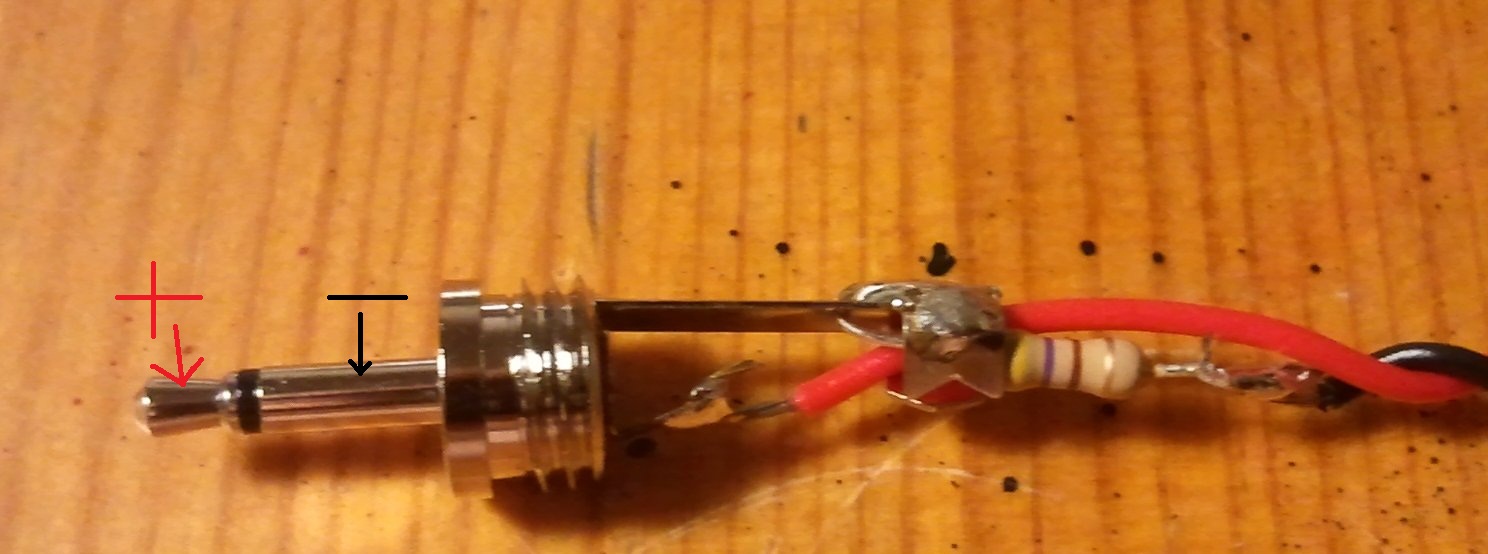
Poke the LED through and once it’s through mark up the bottom of the turret so you know which is –ve and which is +ve. Red = +ve Black = -ve. A touch of superglue will keep it in place.
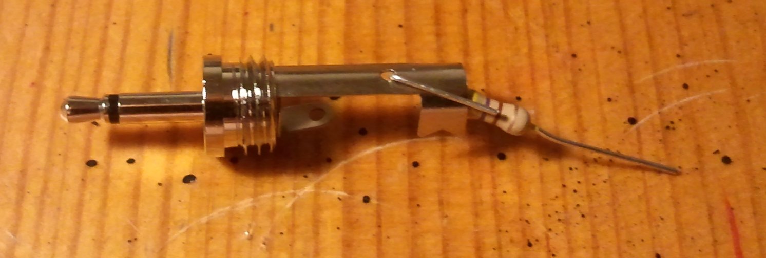
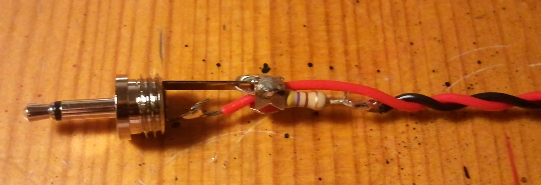
Next get your 470 Ω Resistor, the 2.5mm Mono Jack and some wire, red and black. My advice is use the Multicore wire, you’ll need some play if you want to be able to move the turret after.
Solder the resistor onto the long “Ground” sleeve of the jack,
And then solder on the black and red wires to both of these, black onto the resistor as below
Then solder the Black and Red wires onto the turret onto the pre marked terminals on the turret. Be Careful! This is where you can melt plastic!
The Turret is then DONE!
Well Im back with the next part of the instructions. This time we are starting on the Rhino itself.
Specifically we are going to be installing the Battery Holder, Mono Socket and Switch into the Rhino's body.
Remember how I told you to leave the Rhino in pieces, well I meant it. Since my colour scheme is red and black all I've done is remove the parts that are going to be red from the Sprues of the Rhino, and undercoat them White, before undercoating the Rhino in black with it still on the sprue.
Also to note is that I use the Humbrol, brush on Polystyrene cement. Its easier to use though does in some cases require a "Curing" time.
So onto the instructions:
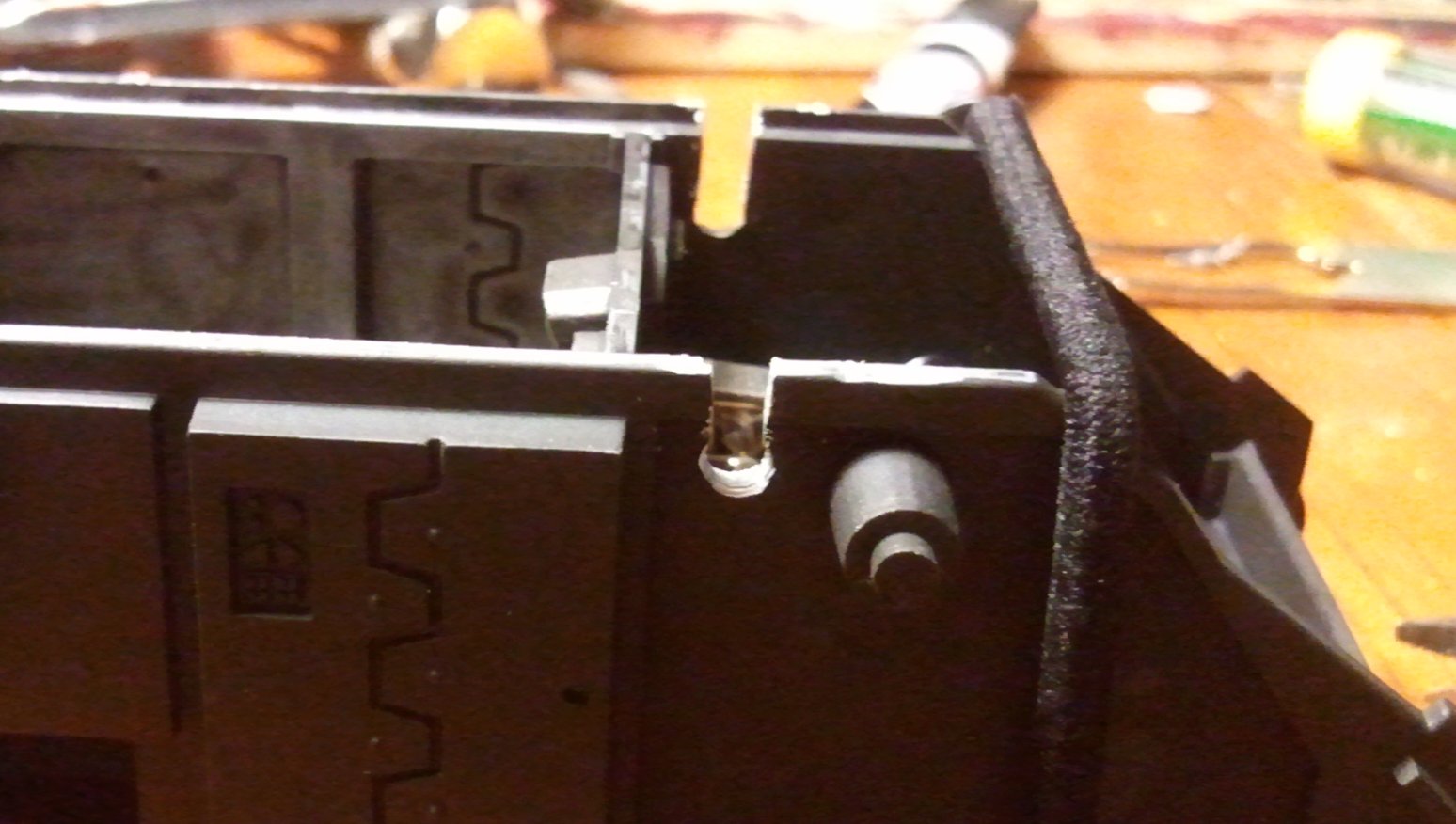
Cut the Driver Compartment dividing wall (The one with the door and Computer terminal) from the Sprue.
Using cutters, a knife and a file cut the Bolt Gun off the bottom. Try to file it so that its smooth and flush with the panel. You'll note that when you do a hole will appear that's about 3mm x 10mm. Which is rather useful
Take a file and clean up that hole till you can fit in the Switch into it.
Cut the Right interior rhino side off the sprue, and slot in the Wall section into it. No glueing yet guys! Mark on the Rhino wall where the switch will poke through.
We're going to need to trim that section off the Wall to allow the switch to be put in place. File it down as so:
Take the inner wall away and glue in the switch with a dab of super glue on the inside, then <em>when its dry</em> drill 2 holes through the plastic to match up with the holes on the back. Then get some wire, about 40mm long. Bend it into the shape below. The distance between the ends is the distance between the two holes you've just drilled.
Guess what comes next? Yep Push the metal through the holes.
Explanation time. The reason for doing this is as follows; as we are putting the switch inside, if the glue fails, the switch will be pushed inside the tank and be somewhat difficult to repair. Thus my using some wire to help pin it in place, we can secure it and stop it from disappearing. Im using that shape as I thought it looked good, but use your imagination here.
Hope this is making sense so far!
When you have pushed the wire through you should bend it back (pic later) to secure the switch.
Next we drill the hole for the socket. Now I made the decision here more based upon ease of use than aesthetics. I decided to use the middle of the door.
You'll need to use the 3mm Drill here, and then widen it out some. Maybe think about getting a complete drill set if you are going to be doing this lots!
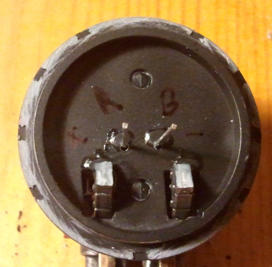
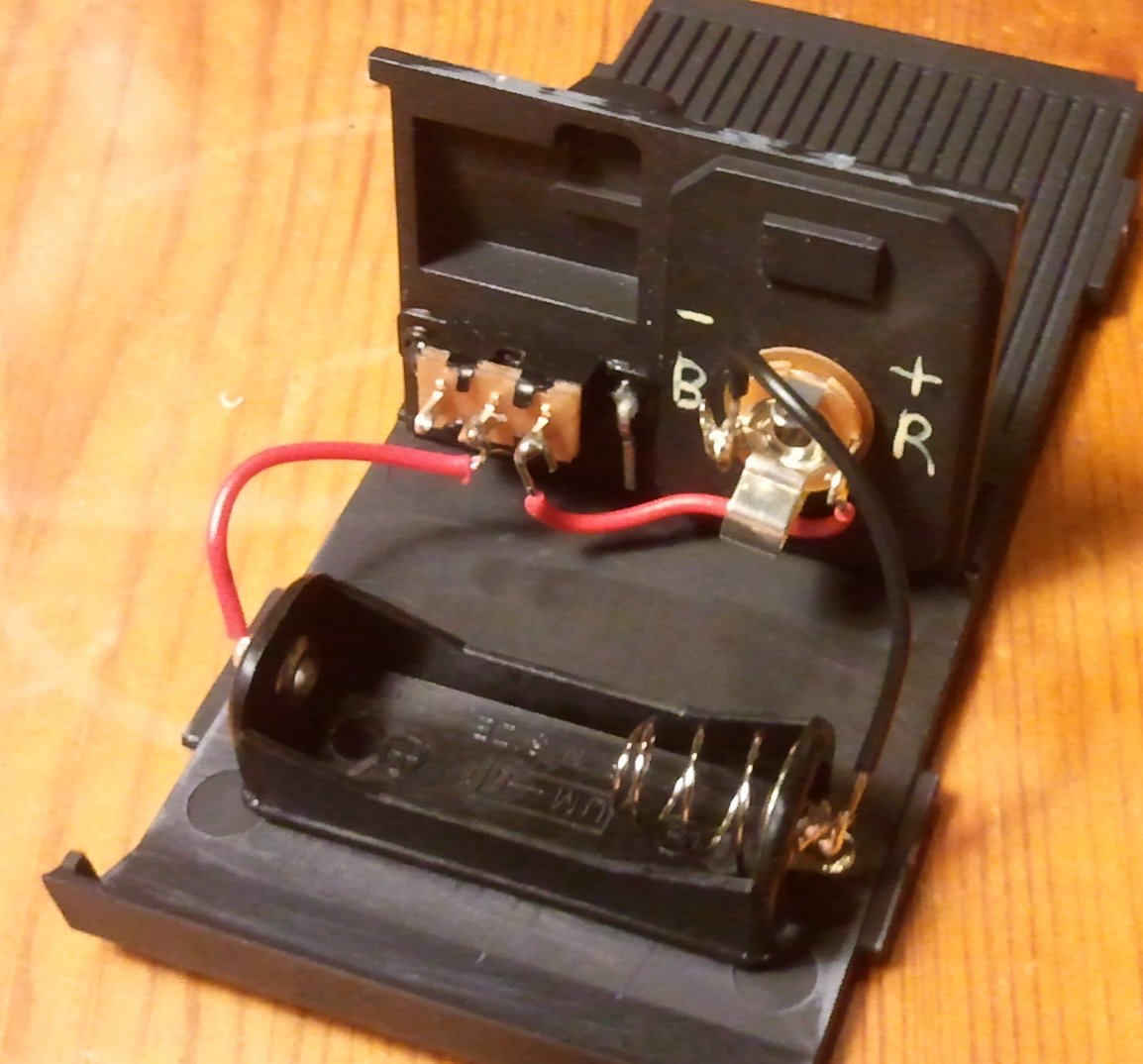
Then Flip over the door and get a brush out to paint some stuff on the back of the door, this is to help us later.
We are going to paint + R and - B on either side of the Socket.
<strong>Electronic important bit!</strong>
We have to make sure than then the 2.5mm Jack is plugged into the socket it is the right way around. So looking at the Jack the tip is Positive (red) and the sleeve section is negative (Black)
Thus the socket has to be wired up appropriately.
Now without knowing the exact workings of your socket, I cant tell you which is which, but you can work it out in most cases by just following the metal. That and plugging in the switch and seeing what touches what! Using that method I found the following, and painted it on the back of the door:
Note the pinned down switch
So next we need to do some soldering. With the Turret already in the bag, it should be easy!
You want to solder the far right terminal of the switch, to the + R, and then a black wire - B. Finally put a Red wire to the middle terminal on the switch.
Ok but that aside for the moment, and pick up the Floor of the Rhino, and the battery pack. We're going to glue in the Battery pack. Since the Battery Pack is made of Nylon, it will need to be roughened up a bit before we glue it with super glue. It helps the glue stick!
Stick that bad boy in! Then go back and grab the Wall with the Socket and the Switch on it and connect the wire appropriately to the terminals, red to + and Black to -
Right. Now thats done you need to paint the insides!
When you have painted it you can stick the various parts together.
NOTE!
Only Glue the Side Walls to the floor and the wall with the Switch and Socket in it. Dont be gluing any other parts now we need them to be free for later on!
Thats it for now folks, I need to take more photos and more work needs to be done before the next post.
However you can check that your turret works! Plug it in to the door socket, put in a battery and switch it on! Fiat Lux!
<strong>Ok Continuing on with the Rhino itself -</strong>
Now Im cheating a little here, something to note is that certain parts when glued together have to be left for up to 24 hours before you start cutting into them an so forth. The light housings are a prime example of this. You want to glue them on to the top armour about 24 hours before you do this following part. The Glue needs to be 100% dry and the bond SOLID!
It will make sense why in a second. What you need to do is work out the very centre of the light within the housing and using a small pin vice (drill) set to about 25mm in length drill right through.
Now if the Light housing is not glued on solidly it will come off as you drill making a complete mess!
Now you have drilled through you need to make the hole larger. Don't be tempted to go straight at these guide holes with the 3mm drill bit, you'll more than likely loose the guide and make a mistake (words of wisdom that I only know because I made that mistake myself) My advice is to use several drill bits in order that are only a bit bigger than the previous one. So start at 0.25mm then go to 0.5mm, then to 1mm, then to 2mm and then finally to 3mm (if you have more drill bits than me, use them!)
If you only have a 3mm Drill bit just go carefully, and wident eh hole a little first using a sharp knife point.
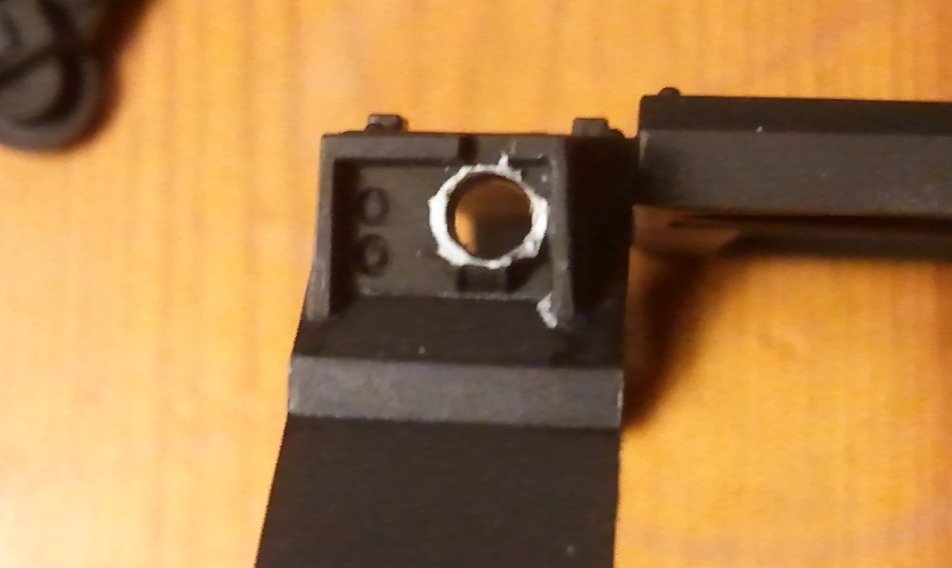
You should end up with something like this:
You'll notice that there is still some of the moulded light remaining. You'll need to carefully clean that if with a knife, or a Dremmel. Id recommend you to paint the inside of the Light housing at this point, so that you dont end up getting paint on the LED.
Right now comes a tricky bit, you need to make the hole on the back larger. You do this by carefully carving bits out with a sharp knife.
Be bloomin careful! I am not responsible for you cutting yourself if you follow this blog! Remember knife safety, always cut away from you and the more pressure you put on the blade the more danger of slipping. Lots of small cuts is the way forward here
In the end you want it to look like this:
Now another method that has just occurred to me as I write this is, is to make the inner hole Bigger to account for the bevel on the LED. This may work fine, Ill probably try it on the next Tank I do!
Anyway, once you have done both sides the same, you need to Superglue in the LEDs. When you glue them in, you probably dont want to push them too far out, as it makes your tank goggle eyed. More importantly the Light Casing directs the light a little, and if it sticks out too much, the light bleeds in every direction. It doesn't look so good.
Note Ive painted the basecoat of the inside of the housing.
Something of note here is that LEDs have different lengths of wire for the anode and cathode. Use the Wikipedia Pic to note this! But in general, the longer wire is the +ve Anode and the shorter the -ve Cathode. Try to glue them in the same way around.
So with the above Ive put the -ve Cathode nearer to the camera on both LEDs. This will make is a bit easier.
So now put the roof aside to wait for the Superglue to dry. Go get the Tank Interior that we built in Part 4
You need to drill some holes in the side walls, inside the Cab area, about 10mm from the top. Use the 3mm Drill, and dont worry too much about their neatness. Then using cutters, cut out the bit above them so that they become a U shaped dip, as below
This is for the wires to go through.
What you need to do is then slot the roof on, and turning it upside down, mark out where the holes that you just made, intersect with the roof. See below:
This will make it easier when we start soldering in the wires. Put the interior aside for the moment, and get that 220Ω resistor. Using some masking tape, put it on to the cathode of one of the lights, and then solder it in place.
You'll notice that I have a bit of flat metal underneath the area Im soldering. This helps protect the plastic from accidental touches by the soldering iron.
then you need to cut some red wire. Remember I told you that there is 2 types of wire? Well for this Im using the single core red wire that keeps its shape. You need the wire to connect the Anode on one side's LED, to the Cathode of the other. You also need the wire to follow the path so that it it will go through the holes we made in the side of the Tank's interior earlier. Thats what the markings are for:
All good so far? Awesomesauce!
Right now we need some of the other wire, the multicore wire that has some flex to it. You need to cut about 100mm's worth of red and another 100mm of black. Solder the red wire on to the wire that comes directly from the +ve Anode of the LED and the Black to the resistor as below:
Then when it is completely cool and solid, its time to do some testing: I say this now as you will be really cheesed off if your little circuit doesn't work when you have glued the tank together wont you?
The simple way to test is to get hold of a PP3 battery, or what people know as a Fire Alarm battery. Strip the ends off the Black and Red Wires that you just soldered on, and then touch them lightly to the terminals on the top, black to -ve and red to +ve. Do both lights light up? If so awesome! If not, Ill get to troubleshooting later on in another post.
mix up some modeling putty or Green and fill in the hole behind the lights:
Right put that aside to cure for about 24 hours. My advice here is this is the point where you want to start base coating the outside of the tank. Get your colours on and fresh. My opinion is that you always paint a tank first, then add the damage / weathering later. You can feel free to glue on the sides to the Tank Chassis now.
Ive just realised that I never properly finished this blog, so heres the last little bits:
Basically you need to finish painting the tank parts. Id say paint the Tracks on the Sprues then attach them. Also make sure you have the roof and so forth painted completely, as one you have soldered on the last of the Wires you are going to have to pretty much glue it together then and there!
So onto the soldering. This bit is tricky, and if you still have that bit of metal as a shield you're gonna need it.
You need to Solder the cables from the roof into the Drive section. The red needs to connect to the switch, the black cable to either the end of the Battery casing, or where the black wire that connects to the turret uplink 2.5mm Jack Plug. To use an electrical term, we are wiring up these headlights in parallel.
The Wiring:
Then a close up!
Now what you have to do is Glue on the Roof:
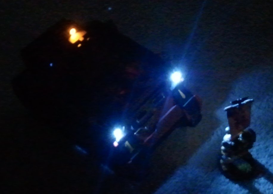
And then suddenly there were 4 of them:
UPDATE!
The Techmarines have been hard at work again and have produced a new vehicle for the Battlegroup Fiat Lux.
(as an aside Im painting up a Blood Angel Force at the moment, because, well erm, I want to?)
This one has pretty much the same sort of design as the Razorbacks with a couple of Caveats:
I have changed the way that the Razorback style turrets get their Power. It seems easier and better for them to get power from their own battery - this means that they do not overly draw on the power in the Rhino, can turn freely, but in a Landraider don't have the wire gumming up the insides. Im kinda gutted I didnt think of it in the first place. The Side Turrets still rotate, though their Light up scanners do not.
Also this time Ive changed the battery pack for the Landraider - and Ive used 4 AAA batteries in series - this is now providing 6 volts, and the flatter pack fits nicely in the Raider. It means that its cheaper to get batteries for, and even get rechargeable batteries. It was also easier to "hide" on the inside, and allow you to still paint the insides.
Finally I am also very proud of the Stormraven that got added to the force
Anyway Im well proud of it!
This message was edited 1 time. Last update was at 2016/07/29 14:46:00
Fiat Lux - Adding lights to Marine Vehicles - http://www.gingerwerewolf.co.uk/ RIP Warseer
Proud Member of the Leicester All Scars
Thanks! Im going to try to add to my light up collection soon - another Landraider. Ive got some ideas for making light up Objective markers to go with the other 2 I made.
Stay Tuned Folx!
Fiat Lux - Adding lights to Marine Vehicles - http://www.gingerwerewolf.co.uk/ RIP Warseer
Proud Member of the Leicester All Scars
This one is very simple - single 9v PP3 With it being 3 LEDs in series. The voltage drop across each is about 3V and thus in series a 9V battery is perfect
Fiat Lux - Adding lights to Marine Vehicles - http://www.gingerwerewolf.co.uk/ RIP Warseer
Proud Member of the Leicester All Scars