This was kind of a spur-of-the-moment thing that struck me while starting this build.
Why not make a tutorial of this? So I grabbed my phone and snapped some pictures.
Please, note that the production-value and picture-quality is somewhat affected by this sudden inspiration.
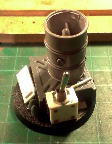
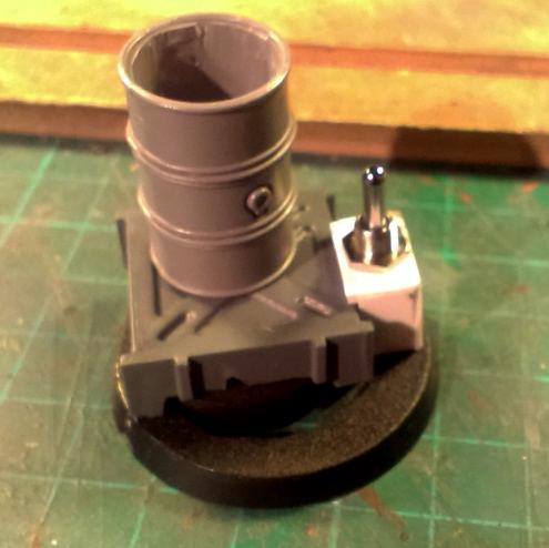
This is what we are building;
 WHAT WILL YOU NEED
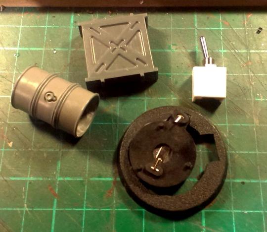
 An oil drum
40mm base
Some plasticard
Assorted plastic bits
Some pillow-stuffing
Clipper
Cutter
Various glues
Some wires (mine is from an old mouse I took apart before throwing it away)
Battery-holder, a switch and a soldering iron (all of which can be gotten at a low price in any electronics hardware store)
Button-cell battery
Flickering LED (This can be salvaged form a cheap tea-light or bought
here)
BASIC CONSTRUCTION I like to put together the basic physical parts first.
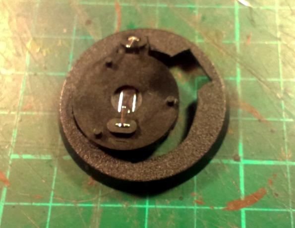
First I cut a hole in the base so the battery-holder, which is thicker than the base itself, can fit through
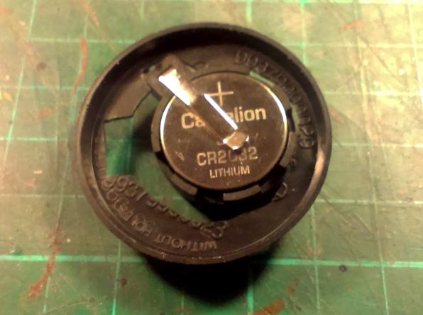
This allows us to easily replace the battery
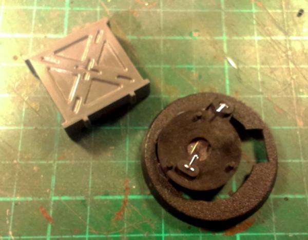
Next I grab anything that can cover the battery-holder. I choose a
GW plastic ammo-crate I had laying around.
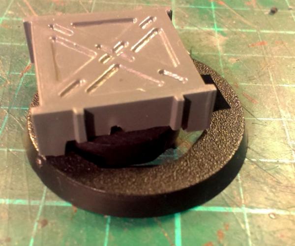
The box didn't quite cover the battery so I had to cut a piece away from the box. Notice that I reduced the height of the box by about half.
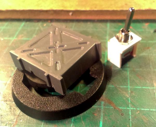
Next I built a small plasticard box around my switch to cover it up. The rectangular hole in the base will allow the wires from the switch easy access to the battery.
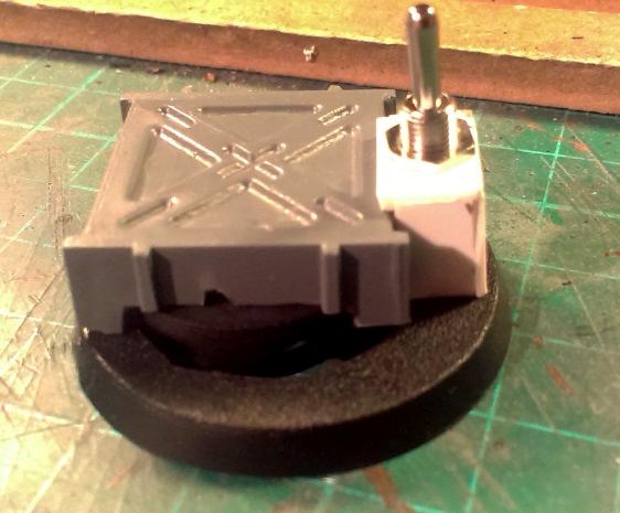
The switch is test-fitted to the plastic box.
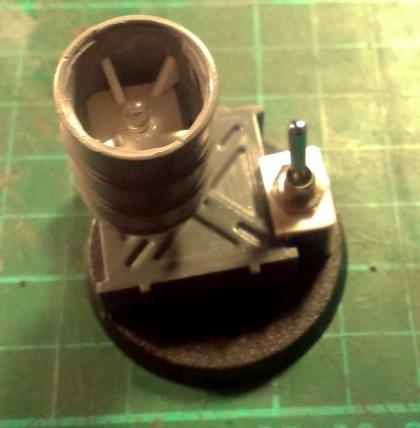
Next the oil drum is hollowed-out and test-fitted on top. I had a
GW oil drum in my bitz box, but any oil drum will do.
The basic physical construction is done.
ELECTRONICS Next the electronics part of the build. Let it be known that I am an amateur when it comes to home-made electronics, and I can't solder worth

.
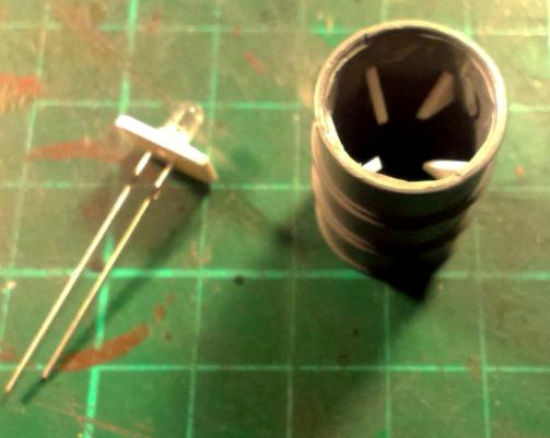
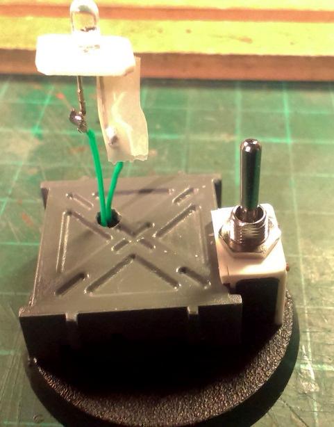
First I prepared the LED. I drilled two small holes in a piece of plasticard and threaded the "legs" of the LED through. Next I glued in a few triangular shapes in the oil drum.
This allowed the LED to be mounted from the bottom of the drum and glued in place.
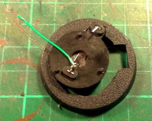
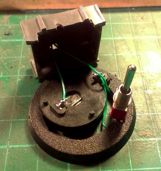
I then solder a piece of wire on the negative pole on the battery-holder. This piece have to be long enough to reach the LED when mounted in the drum.
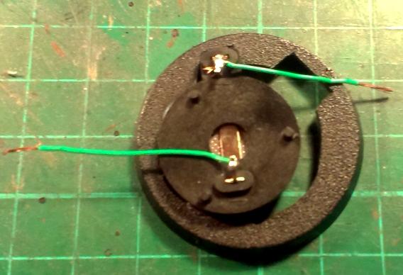
Next we solder on a piece of wire to the positive pole of the battery-holder. This piece will connect to the switch.
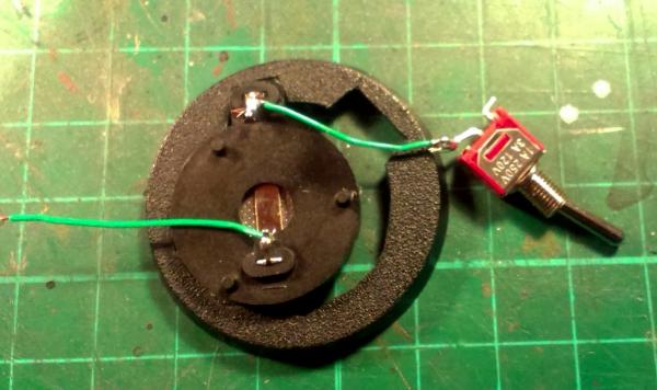
Now I connect the switch.
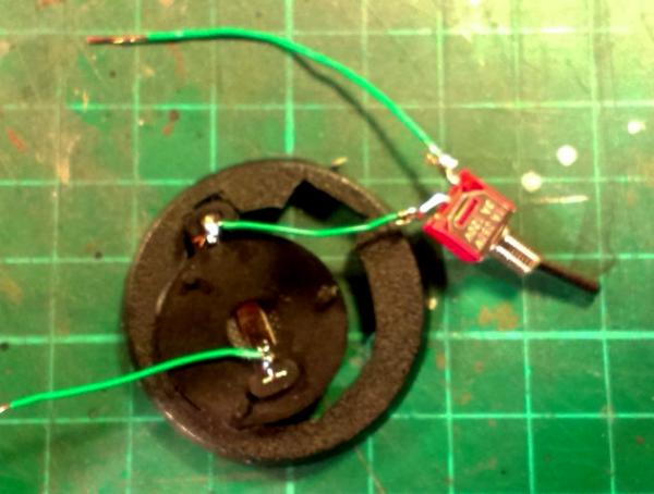
Continuing from the switch I solder on a piece of wire. This piece have to be long enough to reach the LED in the drum.
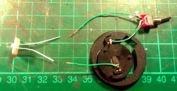
This is how the circuit will eventually be connected. This is a good time to test that the system actually work.
I drilled a hole in the
GW plastic box and threaded the wires through.....
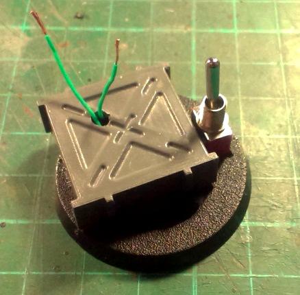
....And glued the
GW plastic Box to the base.
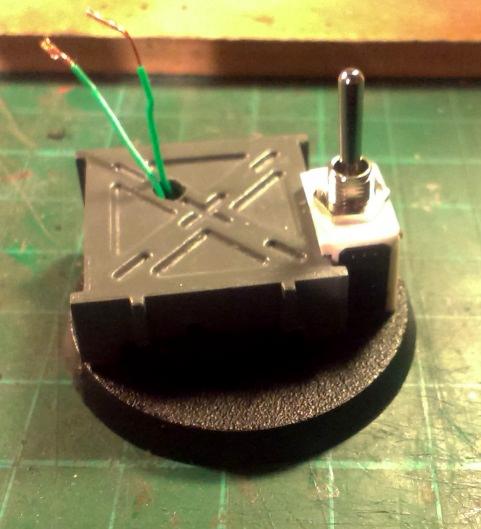
Next I added the plasticard box that covered the switch and glued that to both the base and the
GW box.
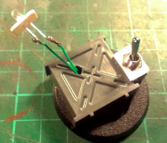
I then soldered on the LED to the wires. Please, note that LEDs are sensitive to polarity, so test and test again before soldering.
As I knew that the wires risked getting twisted when mounting the LED in the drum, I made sure to tape one of the "legs" of the LED to avoid a short.
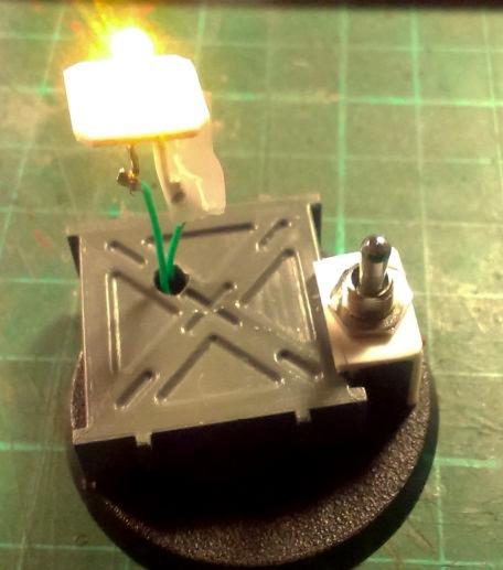
Yeah!...it works!!!

I then mounted the LED in the drum, and glued the drum to the
GW plastic box.
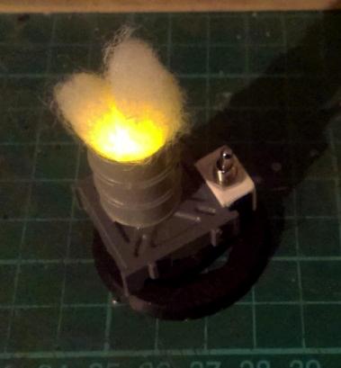
SMOKE EFFECT Finally we add the smoke effect to the oil drum.
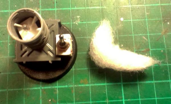
I took a bit of pillow-stuffing and rolled it into an L-shape.
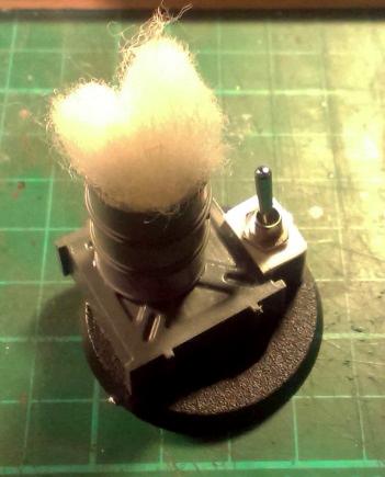
I then folded the L-shape together and jammed it into the drum.
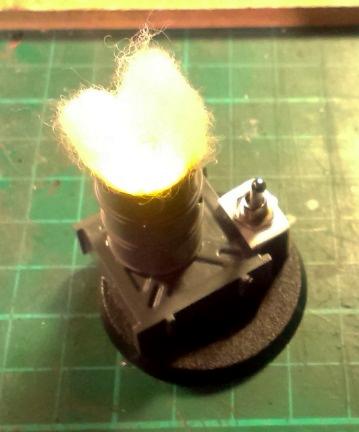
Test!
Test with some of the light turned off.
Before painting I took the smoke-effect back out and added some bits and pieces to cover up some of the more excessive holes in the base, and to make it a bit more interesting.
Now you just need to paint it.
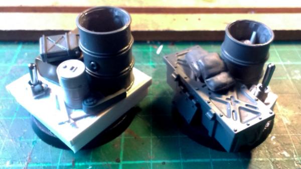
Here are two more examples;
Here are some examples of various other kinds of switches to use as inspiration for other ways to make this (thanks to Chrissy_J);
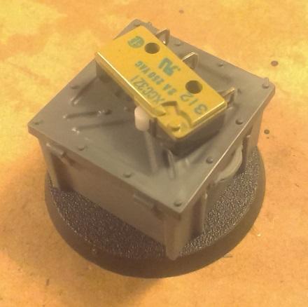
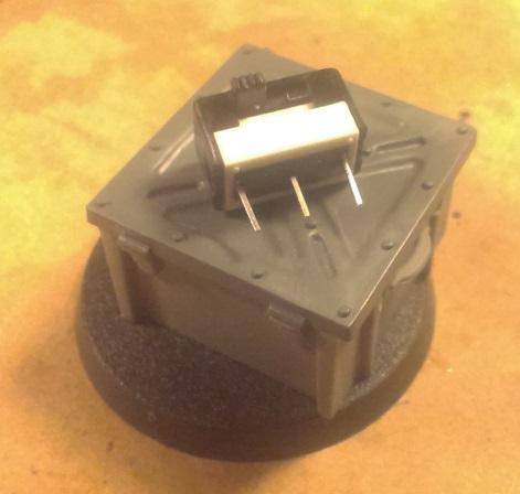
The first one (the yellowish) is a micro-switch. When you press the little white bit the connection is made. When you release it switches off.
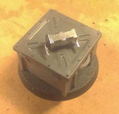
The second one (black and white) is a slide-switch.
The third one (silver) is a tilt-switch. This as also what used to be called a mercury-switch. A little ball-bearing rolls inside to either connect or disconnect.
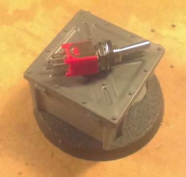
The fourth one (red) is the standard toggle-switch that I used.
Enjoy.


 18.000
  3.500
3.500  8.200
8.200  3.300
3.300  2.400
2.400  3.100
3.100  5.500
5.500  2.500
2.500  3.200
3.200  3.000
3.000


 Waaagh an' a 'alf
 1500 Pts WIP
 IMPOSSIBLE IS RELATIVE
