Forum adverts like this one are shown to any user who is not logged in. Join us by filling out a tiny 3 field form and you will get your own, free, dakka user account which gives a good range of benefits to you:
No adverts like this in the forums anymore.
Times and dates in your local timezone.
Full tracking of what you have read so you can skip to your first unread post, easily see what has changed since you last logged in, and easily see what is new at a glance.
Email notifications for threads you want to watch closely.
Being a part of the oldest wargaming community on the net.
If you are already a member then feel free to login now.
Hello and welcome to my blog on a fire raptor assembly.
In the process of working on this project, I've started thinking about creating a modelling studio. Putting together and customizing models. I've got my interest thread here, let me know what you think. http://www.dakkadakka.com/dakkaforum/posts/list/679942.page Answer is yes, I will be starting a low cost custom modeling company. I'll work out the contracts and pricing range on a model by model basis, but will have examples of the work and what it would cost shortly.
The fire raptor and the storm eagle are sadly some of the most difficult kits from Forgeworld to assemble. The thin walls of the chassis are often warped, the flashing is terrible, and many of the pieces don't fit the way they were designed to.
This blog will be a journey into assembling one for a friend and will allow him and you to keep track of the progress, and the process of this awkward bird.
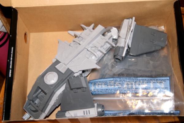
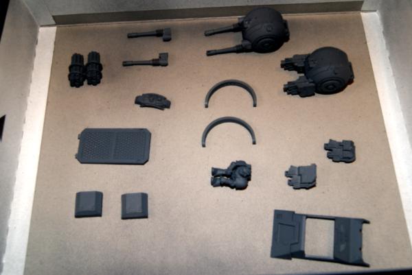
So we had been talking about the assembly process of this fire raptor for a bit, I recently got a storm eagle from a Chinese re-caster, so we were comparing quality of material and cast. Then one day he handed me this box and asked me to help, as he was getting frustrated. Hey GW! Your kits should not frustrate their owners to this degree!
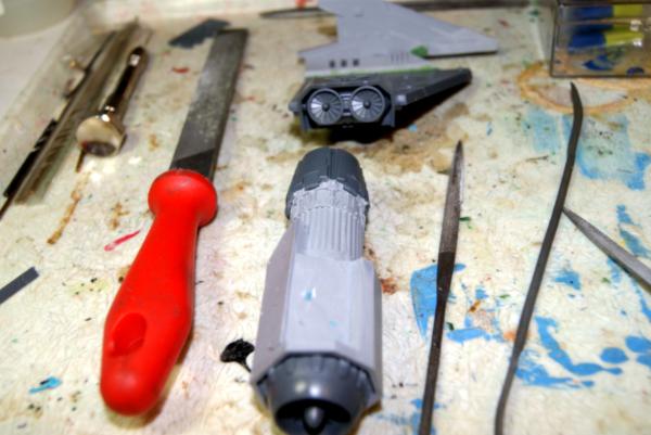
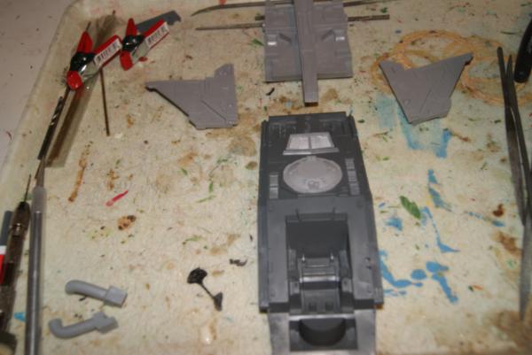
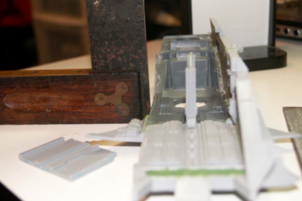
So I looked over the project, and the chassis was just intimidating to start off with, so I attacked a wing first. Luck of the draw we start with the starboard side. I pulled apart the wing from the engine assembly and noticed the lack of a smooth plane. The warping in this kit needs quite a bit of attention, this part wasn't so bad so a touch of file, shiny new scalpel blade, and I thought there was some easy hope here.
Wings and engines:
Spoiler:
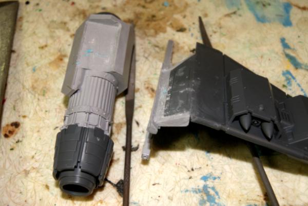
Then I noticed the giant dip in the engine casing.
It looked like it had been dropped when it was hot out of the mold or something. I even held up my re-cast part to compare, this is not a mold issue, it's just a quality control issue.
So I have noticed just hefting the body of the plane and the wings, this is a crazy heavy plane. Like aerodynamically it should plummet from the sky, but actually. It weighs more then a land raider, two, a spartan. More then an average imperial knight. This monstrosity is then supposed to balance on top of a little crossed stand attached to an MC base. Well, let's try and make that a less top heavy prospect.
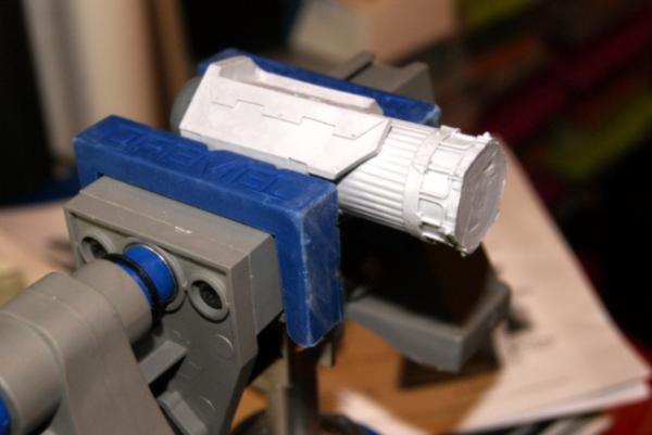
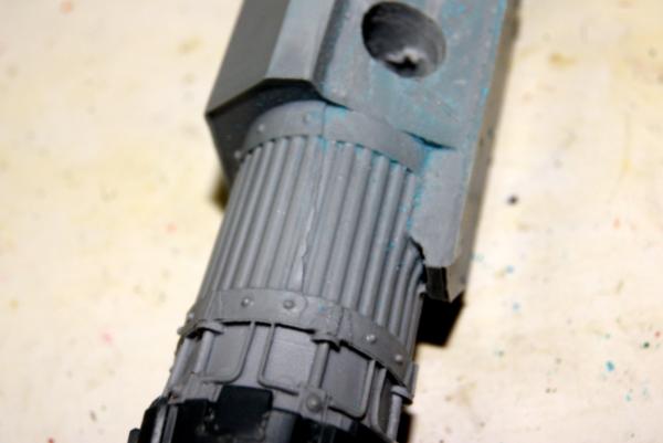
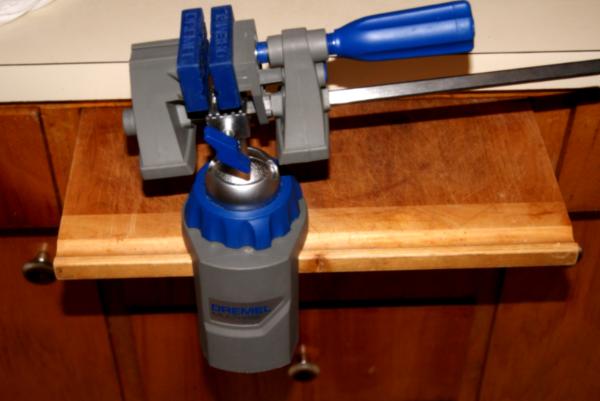
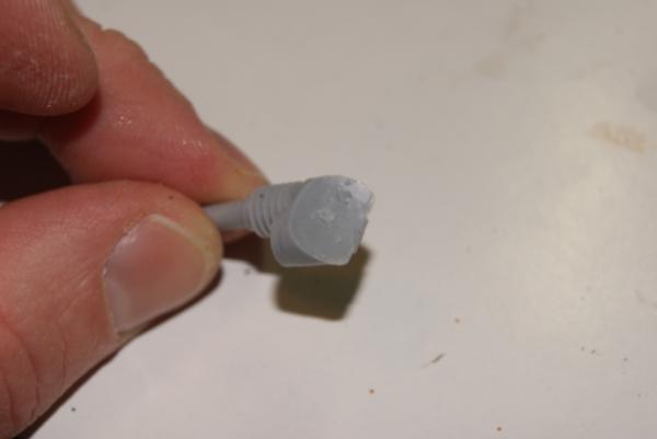
Into the clamp goes the thruster. Say good bye to the rear flaps bit for a moment.
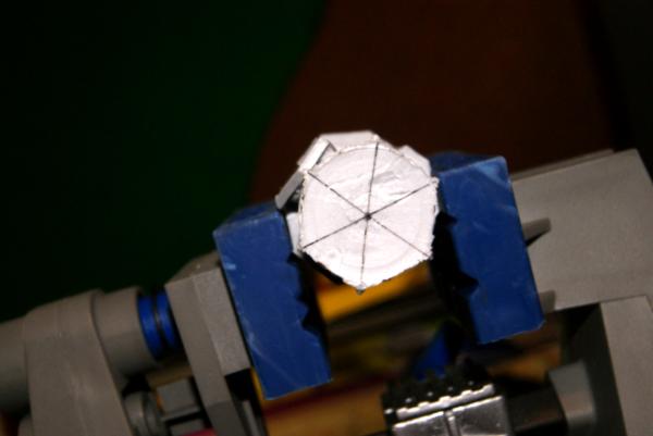
Mark up the rear cross section and find a center point.
Then with a selection of slowly growing drill bits. (Resin is often fragile, so jumping up a size to quickly could shatter the whole thing.)
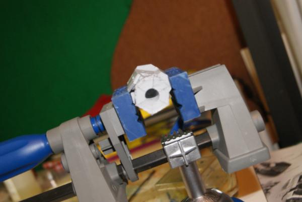
Bam, bored out to 3/8" Not that amazing really, I've seen blogs with them taken to 1/2" I just started feeling a little uncomfortable even with slow moving of the drill bit catching and breaking the walls of the thruster into pieces.
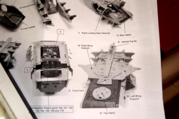
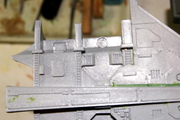
Okay, looking back to fitting, this picture actually is harder to see then I thought. The instructions for the forgeworld assembly. In this picture, the port wing support has a gigantic gap in it. Like a 1/16" gap. That is in the perfect picture for them assembling it at forgeworld. That is terrible!
I cannot fathom the quality control guy passing that piece, or the editor of the instructions being like; "Whoa! That's a huge gap there. Is that how we want it to look?"
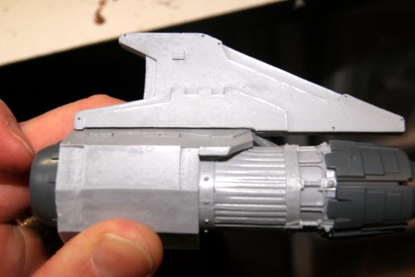
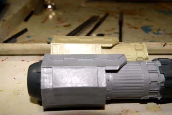
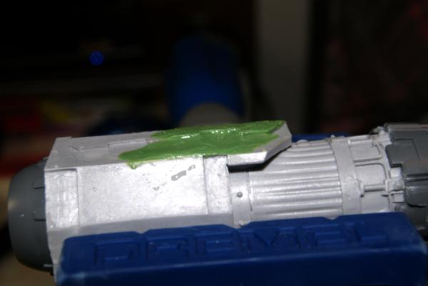
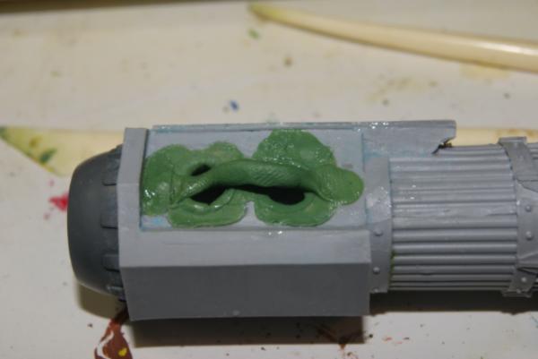
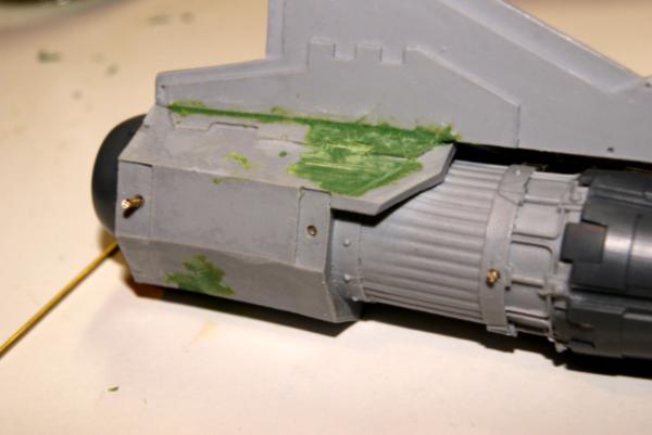
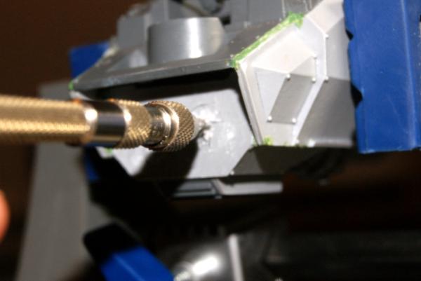
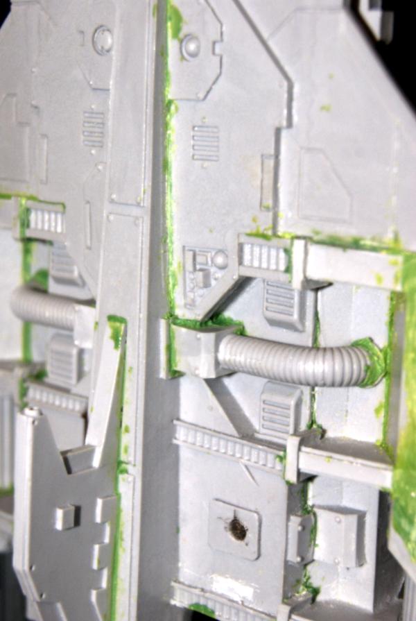
Okay, enough with the ranting for now. Continuing with the starboard thruster, I attacked that big woggle in the armor plating. Green stuff was used to level it out, and to beef up the raised section on the back side of it. I'll come back at this in a day or two when the green stuff is hard with a file and shape it flat.
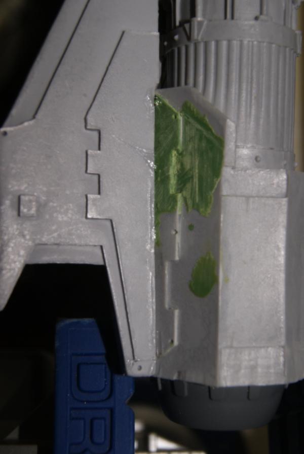
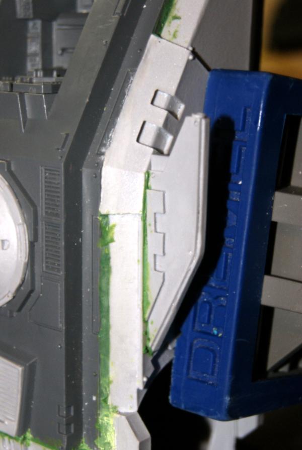
Pretty much a rinse, repeat with the port side, I separated the wing from the engine and cleaned up the wing surfaces. I put green stuff where the resin meets the plastic wing so it matches the other side. Then I removed the thruster end cap and bored out the inside. I'll come back and smooth out the green stuff when it's kicked and put any detail fitting holes back in. The only note with the port wing was there was a pretty sizable misalignment on the mold that created a rift look to the plate. I used my scalpel and a curved jewelers file to smooth that out and then made it level again with green stuff.
A note on these adaptation kits that use resin to plastic. These two materials do not naturally bond right out of the box. Usually both the resin and the plastic have an oily waxy coating or something on them. When I attach them together I will use a damp cloth to wipe them off first (the stuff on the resin also prevents primer from sticking well.) Then if the surface of the joint is small, I will rough up with a file, or even nick the surface with my knife. This helps the glue get in there and really bond them. On a larger surface I'll ad pins. When I don't have enough depth to work with pins. I will create small holes or grooves, put in super glue, and then put in a touch of green stuff as well. With super glue on the other side as well. What I end up with is an increased glued area with a very easy to adhere to surface (green stuff).
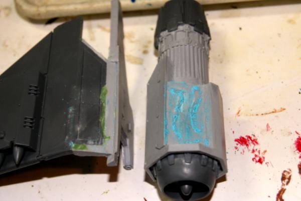
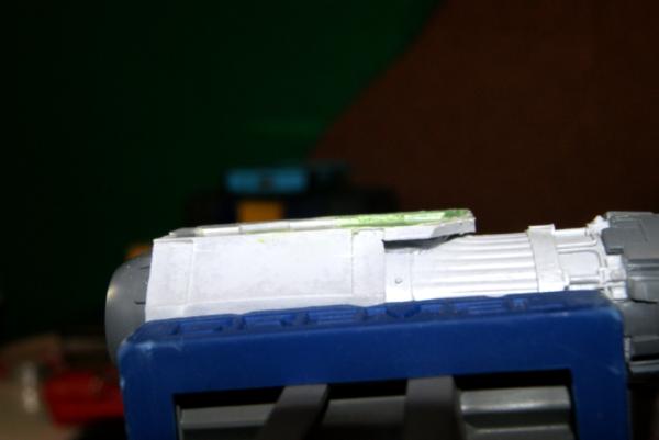
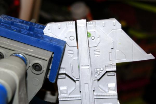
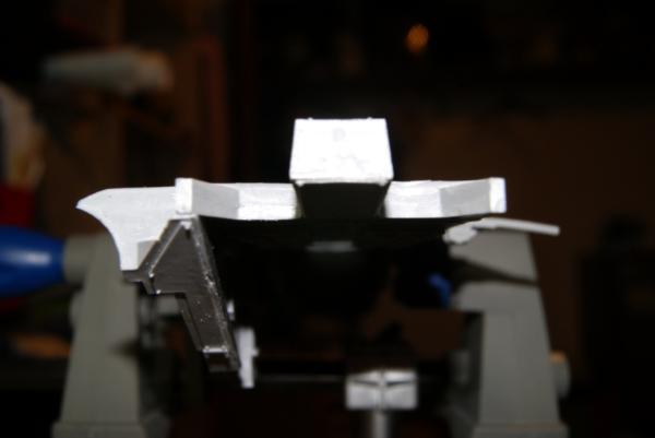
Port wing here I'm getting ready for re-assembly soon, and when I'm attaching large area flat surfaces like this, I want to be sure that there are no high spots that prevent my glue from catching. I can't see into the space as they come together, so I'm using chalk spread on one surface, then observe where it transfers over.
Harder to see in the pic then I thought, but there is a decent high spot in the center, and a couple of ridges around the sides. Rather then struggle with making this a pair of perfectly flat matching faces. I decided instead to continue the weight loss program and bore two more holes into the engine block. What this does for me is give increased surface area, and cross surface area for green stuff to adhere to. A thin layer of green stuff between the wing and engine will level the space out and make for a solid surface. The other option would have been through drilling to pin the wing and engine together. This way makes less weight, and doesn't mar the surface of the wing.
Before connecting these two pieces, I went over the fine details again and saw this miscast in the thruster casing. I cut it down along the barrel and used a gouge to put the space between the rods back in. I'm also going to go over the little space between where the rods go into the thruster cap.
Three days since I put green stuff on the wings the first go around. I find waiting more then 48 hours, but less then a full week has the green stuff kicked and solid, but still a little foregiving. I used my scalpel and hobby knife to take off the worst of the build up, then switched to a broad file for the main portion, and jewelers files to clean it up. The little kick in raised armor pad first was detailed out with the scalpel, and then pointed jewelers file to finish it. I think I succeeded in getting most of the deformation out of it.
From there I went to bore the holes for mounting the wing onto the engine chassis. Here is an important note. We all screw up. the bit bites and digs thru for me here. It is important when these things happen, it is not the end of the world. None of us are perfect, and those of us operating on a toddler sleep schedule aren't even close. Instead of getting frustrated, just think around how you are going to fix it. I have some green stuff ready to go, and it shouldn't be any different from the rest once I'm done. Just cost me a little more time.
Moving on, I got my greenstuff onto the first engine holes that were bored. The idea here is that I have put a touch of glue down the holes, place a ring of green stuff overhanging on the edge, imagine a 45 degree angle to the top of the hole. I then press it firmly into the walls of the hole with a round clay tool. Now press with a flat clay tool to get it as close to smooth on the top as possible. This fills space, but should not be so much that the piece no longer fits. That's next.
I take a rope of green stuff and firmly mesh the two ends at either side of the space. The thick round spot is stretched across and over the two holes. When I compress the wing plate onto here, it will fill most of the gaps giving me nearly two square inches of flat space to adhere with. I place super glue on the green stuff rope, under it between the holes, around the circumference of the plate, then little touches of glue on the facings of the wing that contact elsewhere.
The result is a nice fit, not too much seam left there, in fact less then when I was dry fitting due to the wing settling in with support along most of its contact point.
Repeat with the second wing, and after a little time held in the clamp, I moved them upside down to a safe space. Reason for upside down is, that even though the super glue should hold these perfectly in place, I want to avoid any possible movement or gravity effect on the pieces to shift them while the green stuff kicks.
Upper Chassis:
Spoiler:
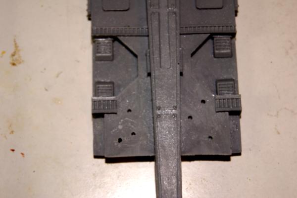
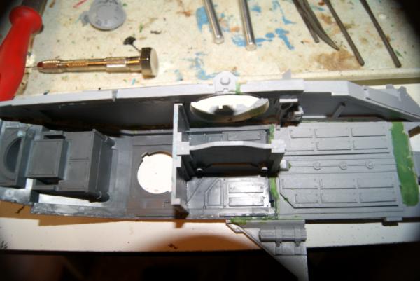
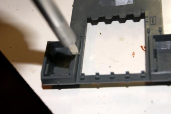
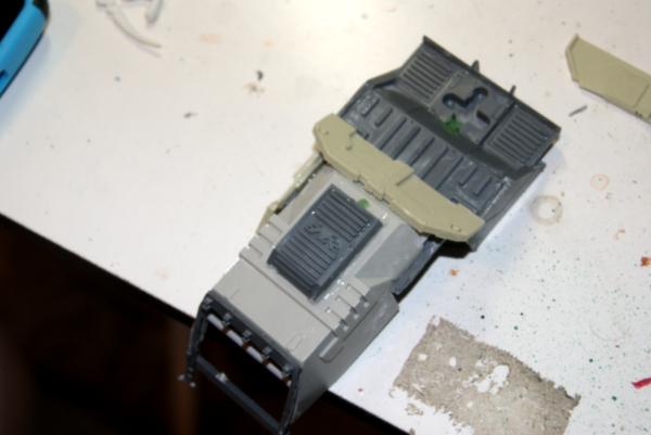
Okay, so working on the chassis while the wings are doing some drying. I took a quick look over it, and really just going to start over. Coming from a wooden boat background, I build from the keel up. (The keel is the wooden back bone of the vessel. If it is strong and straight where it should be, then it will hold together the rest of the vessel. For this beast the beam on the dorsal fin is the back bone. So that is what I need to guarantee is straight.
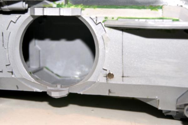
I popped the tail hatch first so that I could get leverage inside. Then using some pressure on from the open rear hatch and where a ball turret will go I removed the entire top of the chassis in one go.
The top of the chassis was easy to disassemble from there. If you need to lever something apart, plastic putty knives from a hardware store are likely to do so without marking up your resin.
So going back to the dorsal fin being the back bone of the plane. I took a look for hogging (when the back bone sags) or any cupping (when the sides of the cast bends down or up). Hogging was negligible when checked with a straight edge, and is almost invisible without it. Cupping, there was a little, mostly on the aft section (rear end) of the dorsal plate. I also found a little bit of super flash. It was so thick that it looked like it was a part of the support edge.
So I filed that down flush with the rest of the parts in that area. I went back to the cupping on aft section of the dorsal plate and smoothed it down a touch with a file, I filled that cup in with green stuff. I over did it here, but will smooth it down when it's dry.
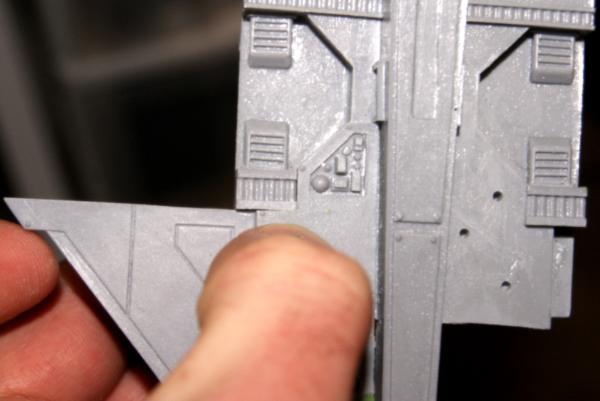
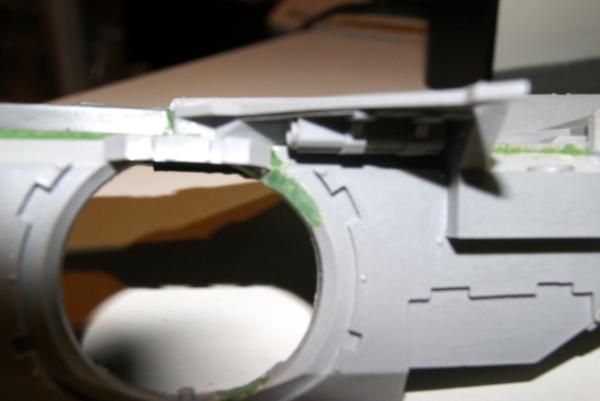
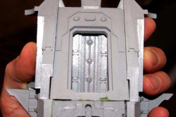
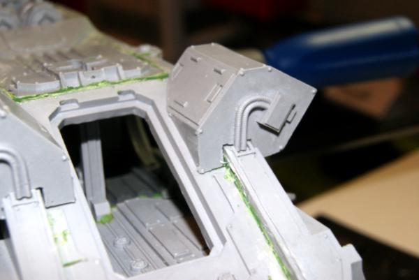
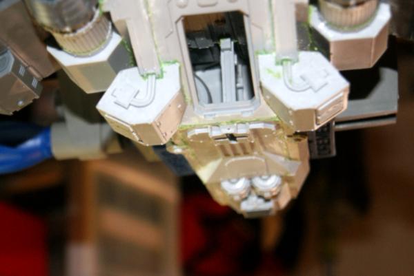
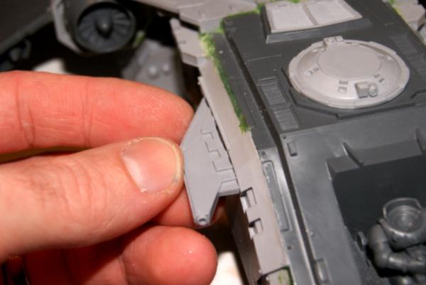
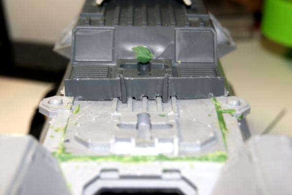
I then tried to dry fit the dorsal plate to the cockpit section of the flyer, that, is rough.
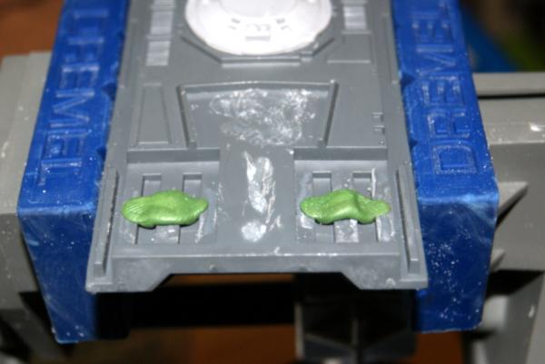
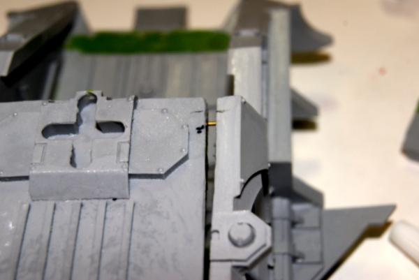
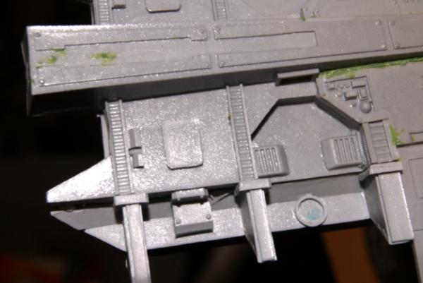
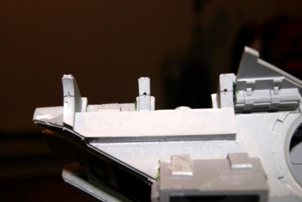
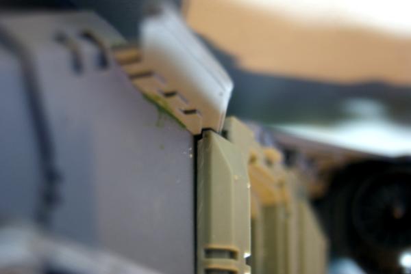
The front of the dorsal fin actually notches into that resin grate that you can see in the first dis-assembly picture. When I do so however, it leaves a 1/16"-1/8" gap. That leaves for a lot of wiggle room to accidentally kink your plane. This means it will behoove me to get the wing supports on next before I try reassembling the top portion of the chassis. Much like with the wing and the engine chassis earlier, I bored holes in the attachment point. Just little ones this time as it is such a thin piece.
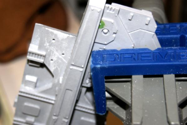
I then dry fit and cleaned to the vents and support on the outside. It will be much easier to green stuff that chasm that is left where the support meets the dorsal fin. I just have to make a flat plane over trying to ad detail.
There was a little bit of warp to the wing support, but not enough to bother heating up water. Instead after I applied the green stuff to the holes and placed super glue on all over. I clamped it carefully in strategic spots. First at the back edge, then in the middle, then finally on what is the front edge.
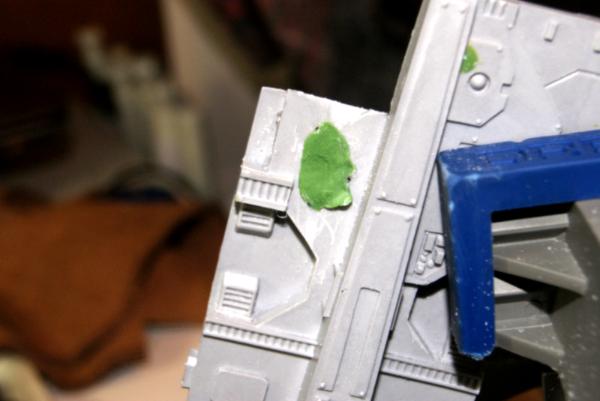
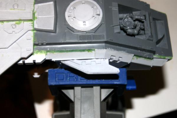
After sitting for ten minutes or so, I put green stuff on the other side. (This is the one that even when tight fit has a huge gap to the dorsal fin.)
Both pieces in place, I left it in the clamp for a bit.
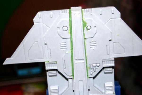
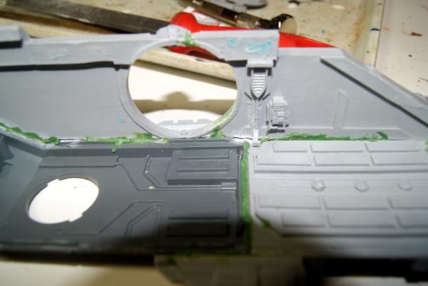
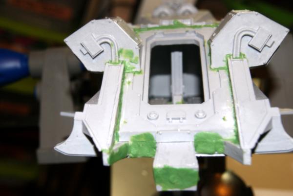
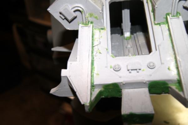
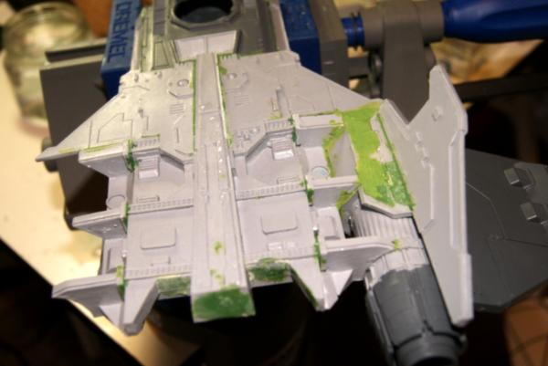
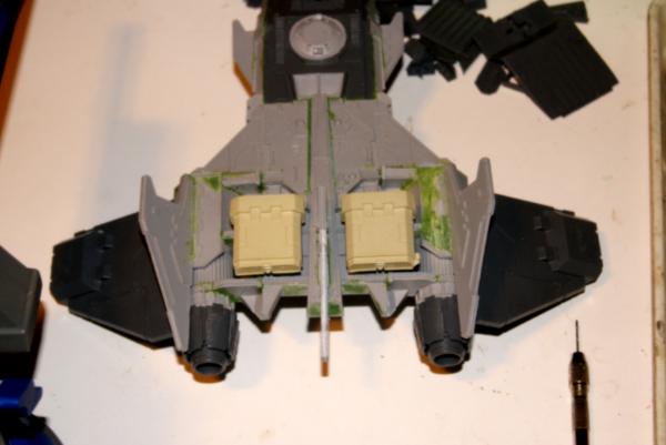
Now with the wing supports in place I added green stuff to fill in the gaps and holes that were left around. As you can see there was plenty of space. Once I filled everything from the top, I flipped it over and filled the bottom as well.
I still had green stuff left over so, I took out all the upcoming pieces and I filled the copious holes and obvious mis-castings.
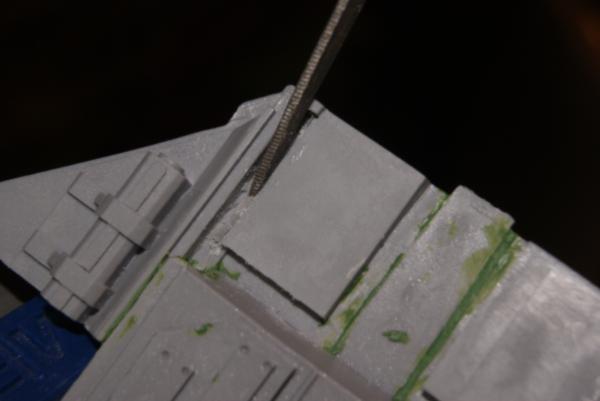
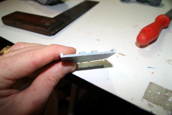
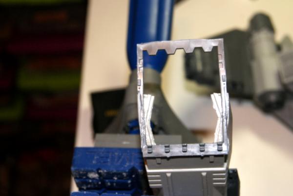
After all the filling had dried a little I began to dry fit the dorsal plate to the cockpit section. My leveling of the pieces has come with a consequence in the tenon squares not seating perfectly into the mortise holes on the cockpit section. So I cleaned out the edge of the tenon piece in the dorsal plate.
I started with my scalpel, trimming to the death I wanted, although this process left paper thin pieces of resin still attached at the base. I cleared these all out with a flat pointed jewelers file as you can see in the picture above. That helped to smooth out what were somewhat rough cuts.
Now with everything dry fit I ad the green stuff that will help fill the gaps in the resin to plastic bond.
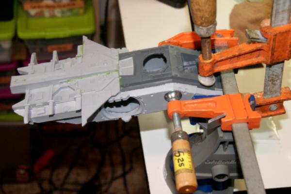
Some nice pressure fitting everything together. I used the vice to hold the larger portion of it and some rubber tipped spring clamps to hold the other side. I have also have a right angle vice and some small C-clamps around, but thought this would give me the best even pressure where I wanted it.
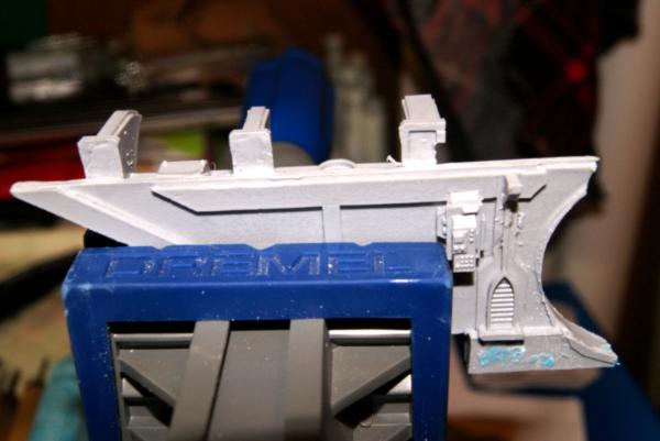
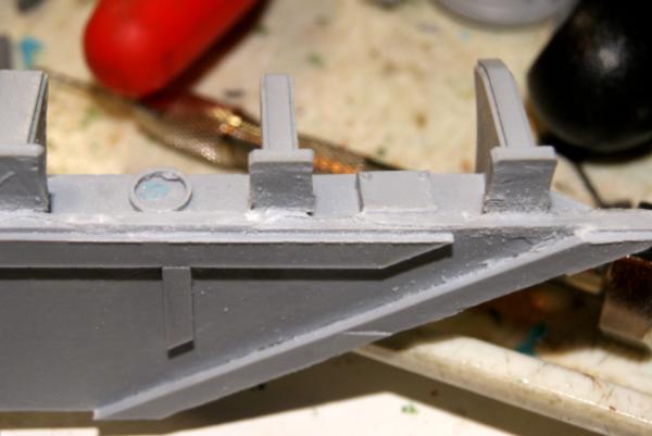
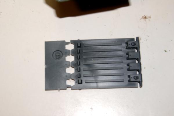
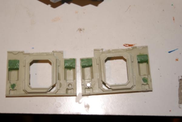
Next is attacking the Starboard side of the fire raptor. The aft panel came off first when I disassembled the chassis, so that's where I'm going to start. There was still a little casting flash, and the upper boarder was not very straight. A good ripple from either warping or excess cast. At the time I was unsure if the owner wanted to paint the inside (he doesn't) so I removed the flash build up on the inside.
Next I put three holes, using my small 1/16" hand drill I piloted into each of the three engine supports that stick up proud. This was followed by eventually a 5/64" bit. I then sunk the three pins into the starboard aft plate and used this to mark the dorsal plate where they met. I used my scalpel to make small marks (fine permanent marker would have worked too.) I then cross those points and find my center. I was out on one of the holes just a little, so I side bored with the drill bit very carefully. I dry fit the pieces to make sure that I wasn't going to catch the lip or something. This was a pretty solid fit, no green stuff is needed initially for surface are bonding.
All glued up I clamped the pieces together (there is a sizeable gap in the forward support, but that can be filled in later with green stuff.
I used a square in insure that the dorsal plate and starboard aft plate were at 90 degrees to each other and held in place. Once it dries I'll ad in some green stuff to fill any gaps and really solidify it's position.
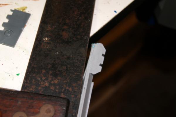
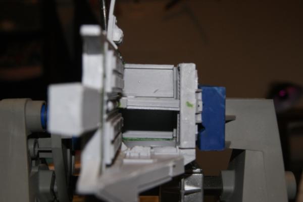
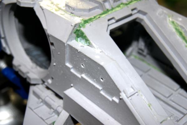
The remaining section of the starboard side has some pretty serious warping to it. I like to check things with my square, and this is pretty obvious.
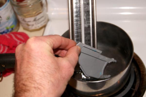
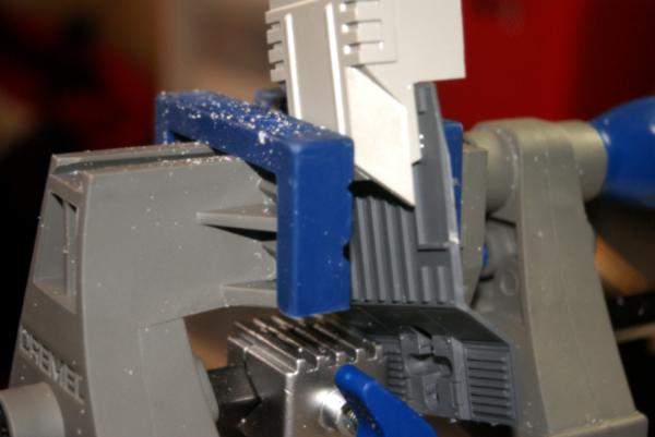
The answer as you may have seen in other how to's is to place the offending piece (only where it is warped) into water that is between 150-160 degrees.
When it has been sitting in the warm water for a bit, the piece is then placed in my portable vice. I sure do love that thing. Cold water can be used to freeze it in place.
After the starboard chassis was all together I filled the various holes and spaces on the inside with green stuff, then came back a day later with my gouge to clean it out and make it look crisper.
I also smoothed out the joints where the ball turret came together post re-attachment. I think when it snapped it must have lost a sliver here and there, as I needed to do some in depth filling on the top there.
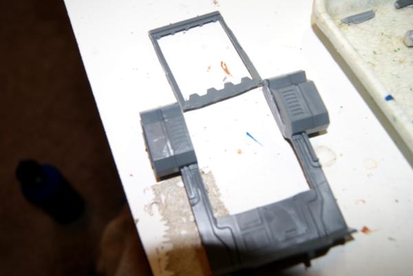
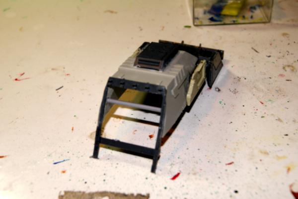
Once you start cooking your resin, you can't look back. All the inner bulkheds the deck, and the port chassis plate were all warped to some degree.
This calls for a new immersion container! Goodwill provided a nice cheap cake pan that does the job for .99 cents.
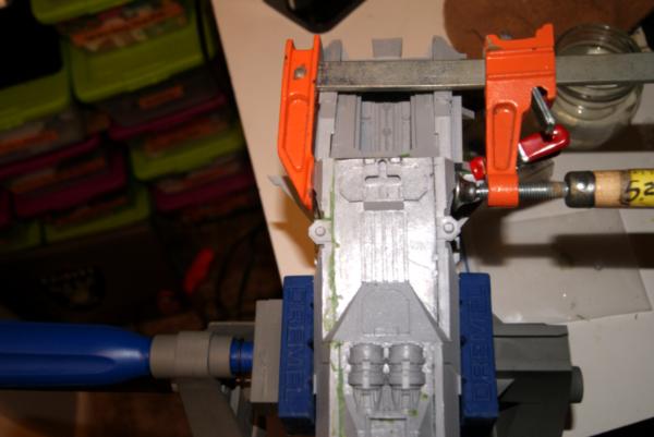
Longitudinal bulkhead was installed first. I used my square to put it in place, getting it as close to true as I can without making a jig.
After boiling the athwartships bulkhead, I attached it, having to tweak the longitudinal bulkhead just a touch to make them all fit together happy. In the process of dry fitting the cross ways bulkhead, I found that it was not tall enough. It is made to have space either at the top or the bottom. Or it was made without the depression in the deck piece that they made. Once installed, I filled a touch around the edges with green stuff where applicable.
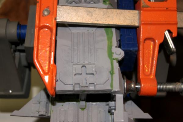
Next up was the deck of the flyer. I was at piece with it needing filling at least a little on both sides after dry fitting it a dozen times and not making headway on the points where it was off. I did have really good contact with the front of it, the ledge at the forward quarter, and aft where it meets the rear hatch panel.
I added a little green stuff bedding to where the internal bulkheads matched up with the deck to fill the space that was left there. Once the glue dried, I added green stuff and more glue where I would clamp at the back end, and re-clamped the whole thing.
I then added the bright orange clamp to hold that after most point together. Remember to clamp very lightly when using something with this much leverage. Closing the clamp and the weight of it was nearly enough to close the gap. Resin when it is not toasted up in water is resilient to dropping, but shatters really easy.
Much like the starboard side I bored holes in the wing and engine support brackets. Here.
I also added a pin in the lower connection point of the port quarter as well. I found that while it was still just a little stand off from the deck plate, it could be easily shifted in, and came nearly true when I did so.
I then spent the next hour dry fitting, filing, and checking the position of the port panel. Just before I went to glue the whole thing in I grabbed the aft plate and slotted it in place. Holy Schnieikes that is bad. It might be the little adjustments I've made to make the rest of the vessel square and true, but even giving that credit, this piece is no where near to fitting.
It is an 1/8" shy from reaching all the way into the slots on either side. The angle for the top of the plate doesn't match the dorsal plate, and the lower section looks like a gag gift hill billy denture set. I rummaged through the other resin bits and pulled out the landing gear, and that explains a lot of it. This piece didn't have to fit great, because the landing gear covers 80% of the snaggle tooth that I see now. However, I'm going to fill all those gaps and make a structurally sound vehicle.
Dry fitting paid off as the port chassis went together much tighter then the starboard side did, much less seem filling on this side.
When I glued this, because there is so much flex in model still, I was able to glue just the top portion, then come back and glue the bottom section. The purpose of doing it that way was I was able to really focus the clamping on making as tight a fit as possible for the bow, as well as the stern. I also added my green stuff to the seams at this point, allowing the whole thing to dry for the evening lightly clamped into place.
You might notice I left the upper hatch above the cock pit off this entire time. While it would have been a rewarding easy piece to attach, that little space allowed for a number of times when I had to reach into the innards of the vehicle and push or pull against the sides.
After the upper portion of the port side was solid, I attacked the lower portion where it meets the deck plate. Plenty of space to ad super glue, and a then clamping.
Clamping pressure primarily focused on the front of the flyer.
The orange clamp added just a touch of extra pressure where the extra pinning was. While it's in place, I added some green stuff. Next on the list is the landing gear, to cover up all the ugly in the back and show me where else I need to ad green stuff.
Dry fitting a bit, these pieces needed a little bit of love, the angles didn't quite match up. (That could be my assembly vs the forgeworld assembly).
Once I was confident in them sitting level and true I bored some holes in both the landing gear, and in the chassis. This is for the green stuff to fit into and create support in all directions.
Square and micrometer told me this was level and true and they match each other longitudinally, but there was still a serious gap forward of the landing gear.
longitudenally
So I attacked the stern of the flyer with green stuff one more time. (hopefully.) I took the opportunity to put some excess so I can carve the meeting of the aft plate and the deck plate, as well as filling some warping on the back part of the dorsal plate.
Oh the amount of green stuff on the back end of this thing.
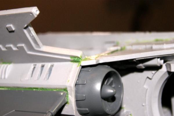
Time for wings! I bored into the engine compartments and into the supports on the chassis itself. The idea is, lining up three pins is tough, especially as blind a fit as this is. So I like to make one primary post, a secondary post with a looser hole. (1.25 mm rod gets fit into a 1.4mm hole) Then the third middle hole is just a receptacle for green stuff that connects to a counter bored hole on the other side. That way they don't have to line up perfectly.
However, it is important to dry fit these a number of times to make sure you have it level and square. Slight file work had to be done on the back of the wing support and the edges of the three engine supports. Then pins installed, I was ready to dry fit and install.
My primary line up point was here on the wing support. I wanted to makes sure that with even contact there, I could have a level wing sweeping back to a solid contact with the aftermost engine support. The two engine supports between were of much less significance for a solid connection.
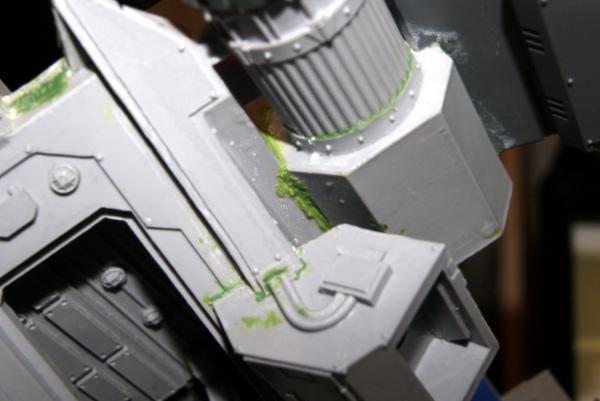
I found that for both of the wings, the level point that had a straight true line for the wings and the engine, I had to shim the wing about 1/32" off the chassis. This resulted in quite a bit of green stuff work as soon as the super glue holding it was in place. The starboard wing here was done without any green stuff boring holes in the large flat surface where engine meets chassis. I added four holes in the other side.
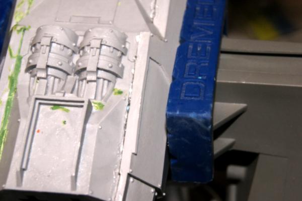
Now that the wing was in place I took my time smoothing out green stuff around the entire mounting surface of the wing, and blending in the minor sculpting edges needed. I also added another smear of green stuff to the top surface of the engine piece. (This is the one that looked like it had been dropped while still warm out of the mold.)
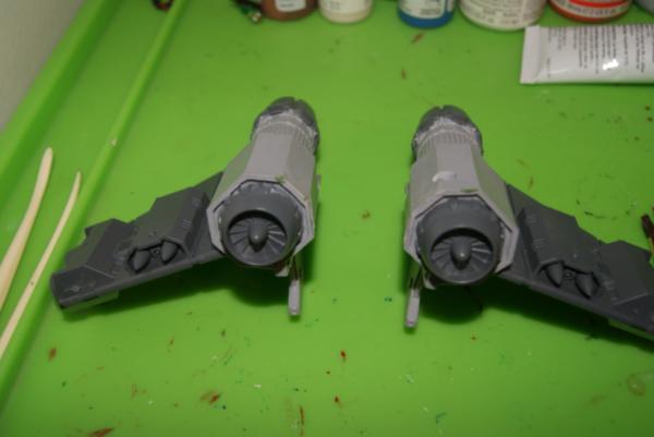
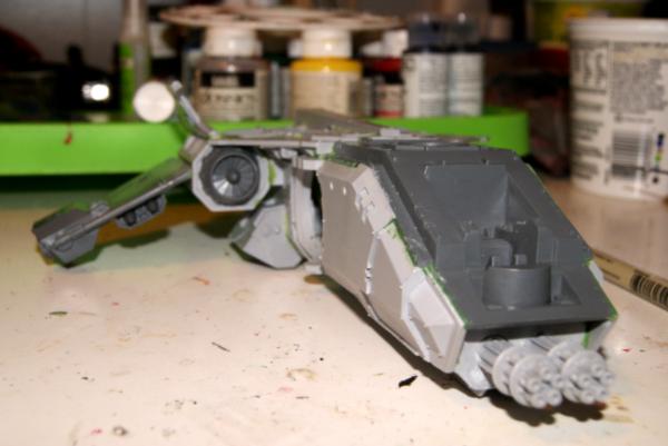
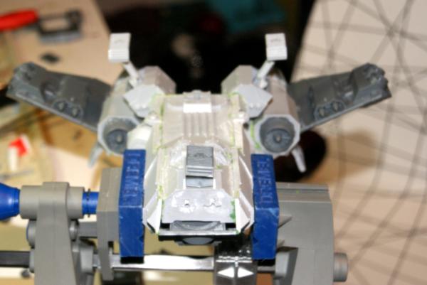
Tadah! First wing is attached. A couple hours passed and I set it down on the table and it looks pretty straight there, less then a .01 of a drop according to the power of the micrometer.
Everything done above was repeated for the port side, although I added some more holes to that flat space on the engine as I said above. I also did a better job shimming and pre-green stuffing the space since I knew it would be sitting off the chassis by that 1/32".
That will be it here for the Chassis aside from a little clean up on the green stuff after it is all dry. Next will be breaking into the various small projects such as weaponry, cockpit, and any special work I do.
Weaponry:
Spoiler:
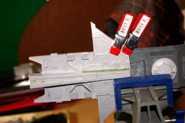
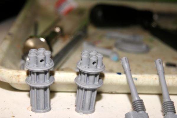
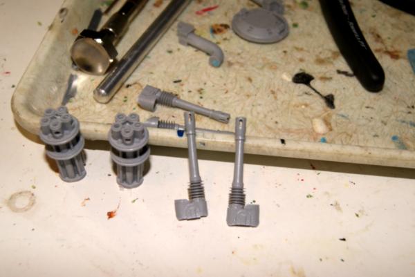
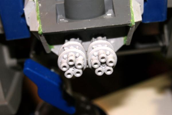
All right, with the chassis mostly done and I'm watching some green stuff dry, I thought it was high time that I started looking at some of the other gear for the fire prism. I'm aiming to do the little things with this project, partially to show off attention to detail for those interested in hiring me to build their kits. So here come the gun barrels. One of those little details that really helps set a model apart is taking the time to drill the gun barrels to a point where you can't see the obvious filling.
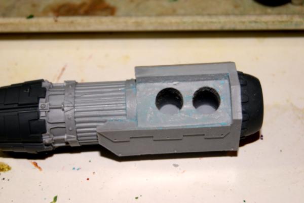
So first I drilled out the cross venting for the rotator cannons, then bored about a 1/4" past the same vent from the end of the barrel. I used a 1/8" bit.
I then did the same thing for the auto cannon barrels. Although different bits. A 1/16 inch bit for down the barrel. I used a 1/32" hand drill bit to clean out the vents. I think it really makes the weapons look that little bit snazzier.
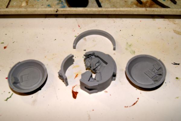
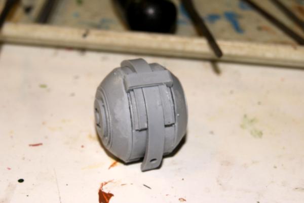
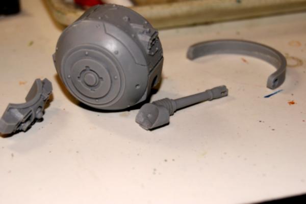
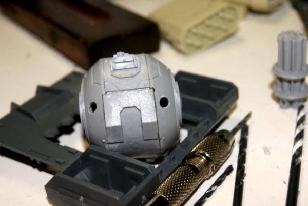
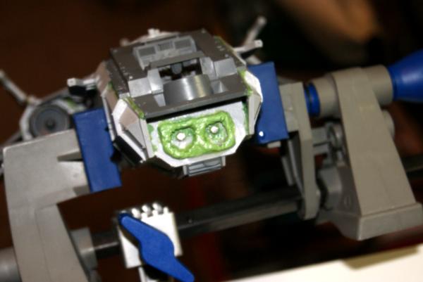
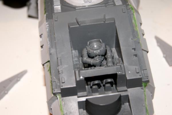
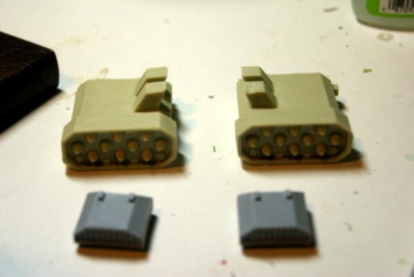
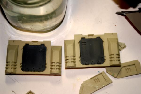
Next up is the ball turrets themselves.
There was a little bit of miscast here, small ridges and the parts mostly fit together. The front panel in fact was perfect, slot sliding in and the teeth meshed on top. The slot space would work pretty well for a hinge were I aiming to make the turret open for seeing the guy inside. The space would also likely fit an led system pretty well.
The biggest issue I ran into, with both of them was the panel to the left of the gunner. The plate lines didn't line up. I had to remove about 1/16" from the bottom of the notching edge.
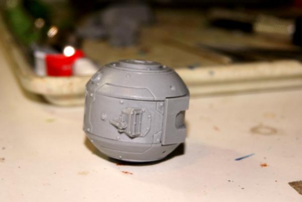
Once the ball was together, there were some proud edges, especially around the back. (Since I was matching to the plate lines.) I cut and filed these down so there was a pretty uniform angle change around the whole of the ball. I'll come back and fill the gaps that were left when I do the next smoothing.
A part that I missed in the initial picture is the clamp that holds the vertical slide in place while still allowing it to move. It needed a little trimming and that was it.
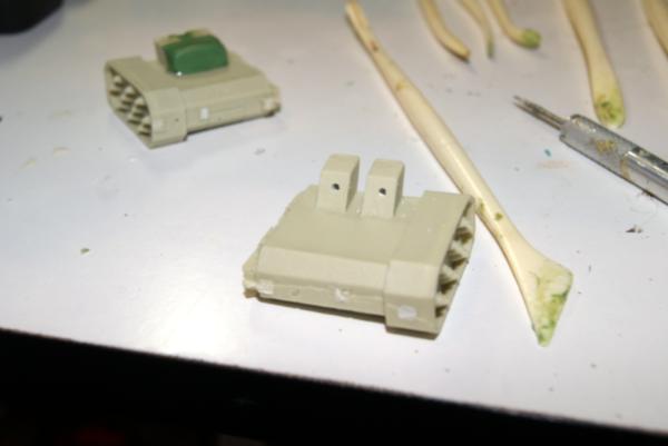
Now I'm looking into the future when I do the magnetizing. Looking at the auto cannons in particular, there is a convenient divot and bump that fit together. This is where I plan on drilling to ad the magnets. (They are on order.)
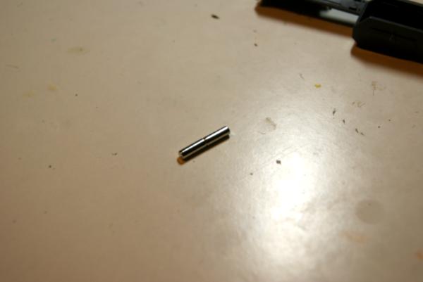
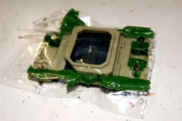
First step with the magnets here (I really like the somewhat standard holding power of 1/8" based magnets. I probably could be using a smaller diameter of magnets, but the practice holds the same, and I have had issues with going to small and having insufficient holding power.
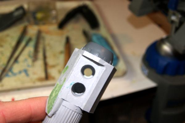
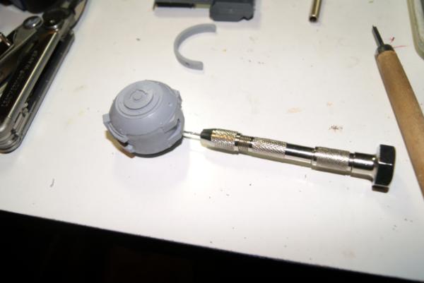
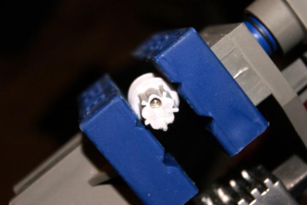
The ball turrets have a very convenient divot that I used as the set for the fine hand drill.
I slowly worked up to the 1/8" hole in three additional steps.
As soon as I finished the drilling however, I noted that there is not a lot of material there. I could get a decent magnet hold, and could have placed them at right angle to face of the gun and ball turret. However, I really like to socket in. What I would have done in retrospect is drilled the holes and installed the magnet before I put the ball together. It would have been pretty easy to ad a green stuff socket for the magnet to seat into, still leaving a good mortis for the weapon magnet. As it is I'll very carefully ad some green stuff through the 1/8" hole and re-bore to create a solid seat for the magnet.
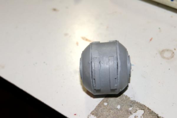
Next I used my small gouge to unseat the ball in the auto cannons.
(this picture didn't want to load for the moment.)
After working the ball out it left a nice little point for my drill bit to bite into and pilot with.
On the bolt cannons in front I drilled down the "top" barrel to set the magnet into about 1/8" deep. A note, when you are putting a tight magnet fit into a hole, you are creating pressure with the glue inside. Simple solution, bore a very small hole at the bottom of your socket for the excess glue and air to escape from.
On the chassis I installed those nice long 1/8" X 3/8" magnets, however I did this at night when I was too tired to read anymore. (So I thought I could model?)
Well the instant I finished gluing them in place, I attempted to attach the cannon and the magnets were reversed. Polarity was off. Doh! Usually with two weapons like this I do one reversed to the other, helps prevent you putting the wrong weapon in the wrong spot. Well I forgot on the chassis, but remembered on the cannons. There is no chance that I can get the magnet out of cannon without major surgery. So we will do some minor surgery instead. Using my pin drill I hand drilled around the entirety of the magnet adding 1/64" hole around and three quarters of the length of the magnet. Being proud to socket into the cannon it was easy enough to grip the end of the magnet with pliers and slowly rock it back and forth until I had broken the glue bond.
A note on drilling magnets. In general, don't. They are very hard and thus brittle. They don't tend to bore out, but instead fracture, and this will catch your bit, and often result in your pilot drill breaking. Much easier to remove the plastic/resin around the magnet.
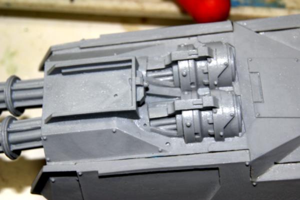
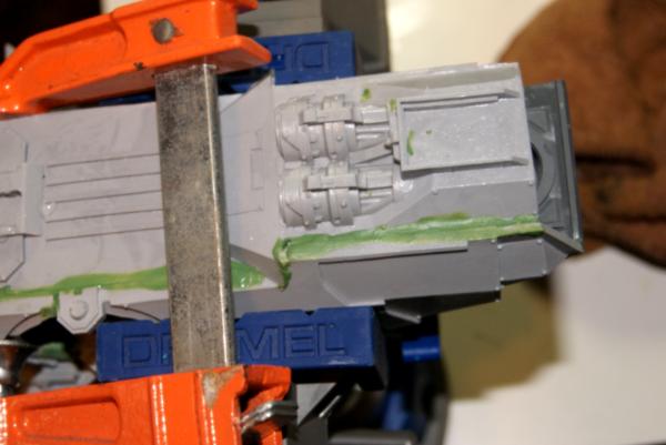
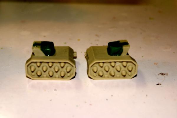
With the magnet in the right way, the auto cannons rest against each other almost. I added a drop of glue between them, (yay surface tension) once they were true to each other. I'm going to ad a little box at the base of the cannons as well in green stuff. To help them seat better around the magnet.
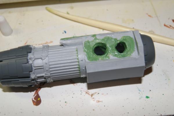
The cowling I added was pretty rough at first glance, just a pair of rings around the where the cannons go. Then wet the cannons a bit, set them to their magnets and moosh the green stuff around it. Removing the wet (thus they don't get stuck) bolt cannons for drying.
I then came back with knife and gouge, cleaned up the rough edges, made the box shape I was looking for and leveled the top of it. There was some wasted material, but it would have been pretty difficult to get into this space with tools when the cannons were there. Once it was cleaned up I glued the cannons shroud into place, and covered the gaps with green stuff.
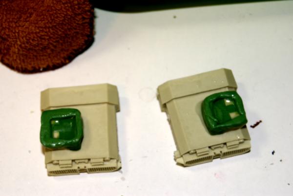
I then jumped over to the ball turrets again, with the green stuff that I had placed inside the drilled holes, I used the 1/8" bit by hand to slowly clear out a deeper cavity. A power drill likely would have just ripped it off the walls. I then placed the magnets using a pipette style nozzle on the super glue to coat the inside of the ball turret holes, and then attaching the magnets to the auto cannons as handles. This allowed me to tweak and place pressure where it was needed to get the magnets just right for their gun.
Landing gear and extras:
Spoiler:
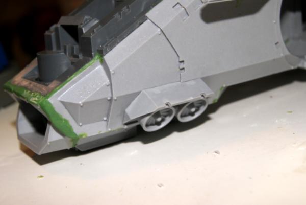
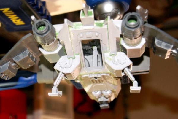
Taking a look at the landing gear and if it should be up or down. For landing gear retracted, it's super easy to get a look at before hand. I placed the three pads into their spots (note that the forward one is wider then the two in the back.)
Took this picture from the front with the raptor upside down in the vice. (Yay gravity.)
The second picture I flipped the camera upside down, but it's still in the vice, I promise.
Next was with the landing gear extended. A little tougher with the rear as they extensions are much longer, and the feet are canted at about a 60 degree angle. From a hydraulic engineers perspective, that is poor design. (Like anything in the 40k universe consulted an engineer.) A note when you don't want to superglue something in place just to take a look at it. Use a putty knife to remove the bits and pieces of un-mixed blue or yellow parts to your green stuff. This acts like a hold em clay. Just put a little bit in place and smoosh. You won't get perfection as your taking up some space, but you will be able to make it work.
From the front.
Upside down from the rear.
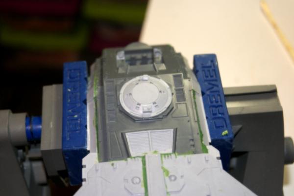
Small things to put together. I attached the hatch to it's hole. In the potential future conversioning, I may ad a magnet to the top of this in the center, which is where the storm raven turret would attach.
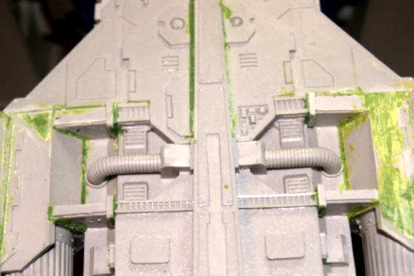
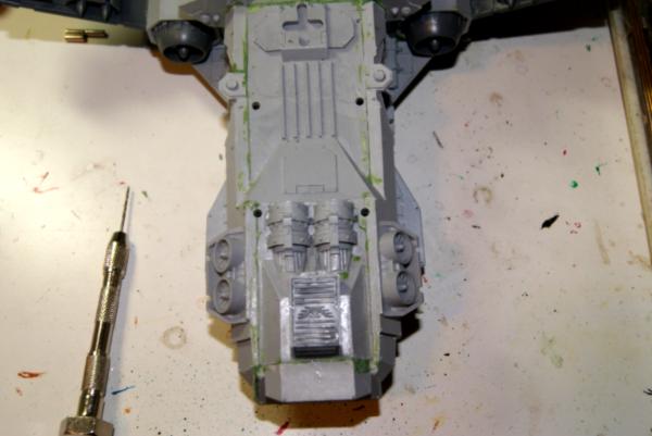
While I was doing the little things I added the center dorsal fin. A square helped make it straight. I didn't feel the need to pin this, but since there are gaps, I'll tuck some green stuff under it when I hit another batch of filling.
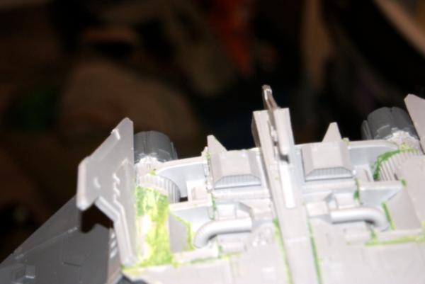
How about some vent umbilicals. I noted that they didn't line up with the cups that are present. They are just a touch long. The solution, file a touch off the box at the other end. It sets deeper into the dorsal frame and lines up better. There are plenty of gaps here though that will be hit on the big go around.
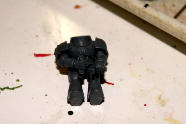
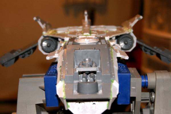
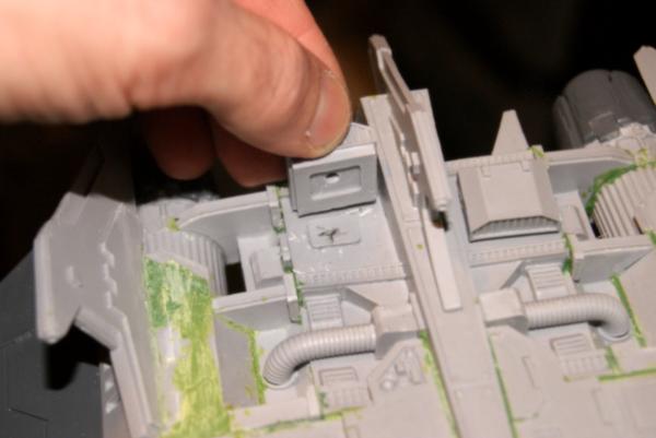
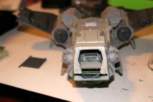
Started work on the cockpit. I began with gluing in the backrest. It's kind of nice that this is a simple piece to put in with the smooth plastic backdrop. It makes removing flash or any mistakes a non-issue. Then I installed the control panel. The pilots arms are positioned based on the control panel, so it's worth the in and out hassle I think. With the back panel in place (I did not have it there for dry fitting.) you just put the legs in place, rest the torso naturally, and then once the legs and torso are together it's easy to hold one army while it glues to the shoulder. Repeat with the other side.
In fear of glue dripping, when I did the shoulder pads (they fit loose.) I removed it from the cockpit and glued them on the table. The pilot has to be finessed in and out, but does move about for the ease of painting.
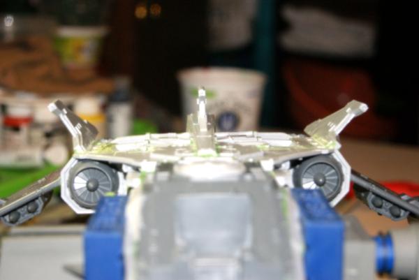
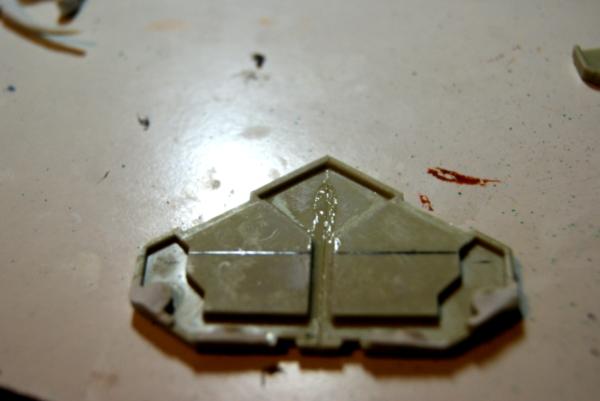
Bow fins for the hull were next. To me these things really look extraneous, too much flat space for GW to leave it alone, so they added these awkward fins. After a touch of straightening in the bitz Jacuzzi, I dry fit them and found another lovely gap. These have a ball to socket flat joint, so it's easy to glue them in place holding them square, then come back to fill in the gap.
The largest gap was on the starboard side.
Once installed I felt like the port fin was substantially larger then the port one. It just didn't look right. I actually removed them both and set them on top of each other. Same piece. I reattached them and measured to every nearby surface on the plane and they matched to within 3/100th of an inch. Measured vertically they matched.
I eventually looked around the net at other pictures of the flyer, and in each one of them the port fin looked odd to me. Perhaps it's just something I'm noticing, or consistent with the angle of the camera that people are using. (Including myself.)
Vents are next! Actually, since they are for the storm eagle work, I'm moving this to the MOAR conversion section.
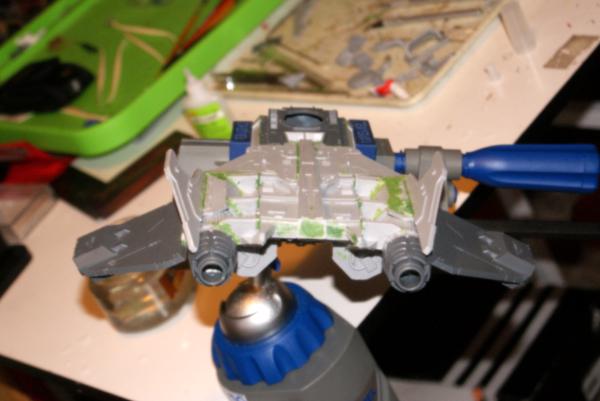
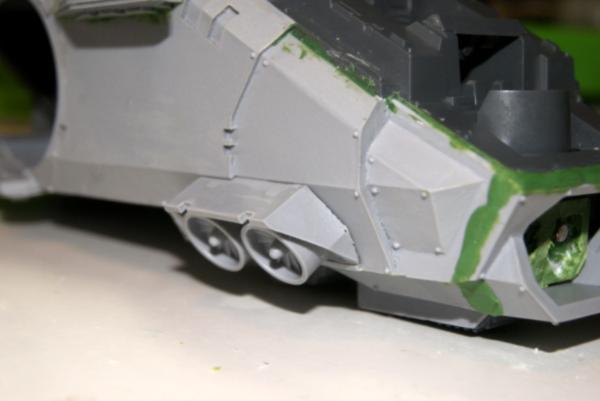
Back to little stuff. With most of the work requiring clamping is done, I'm finally installing the rotor thrusters for the bow. Just some simple glue, these were probably the best fit on chassis assembly the whole time. Just a little filling needed at the forward edge.
I added green stuff around the umbilical boxes, and various other small spots that had accumulated as I put the details together.
Bow fins got filled as well.
Moar conversion!
Spoiler:
Okay, this is going to be the spot where I start to explore the real possibility of magnets, sculpting, and spare parts making it possible to switch between fire raptor and storm eagle on the single model. With an off chance that even the storm raven is possible.
So I didn't really pay a ton of attention to the bag of plastic GW bits until I was starting to think of the process in magnetizing the guns. I had already pinned and glued the big rotary cannons in place, but I thought. Hmmm, I could make those magnetic.....
Then I started working on the ball turrets and I have noticed, they can be made pretty easy to remove....
There are a bunch of big pieces of plastic with grim darking all over them that could be used to make a hull extension, even complete with assault doors....
This might be possible.
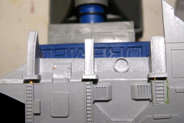
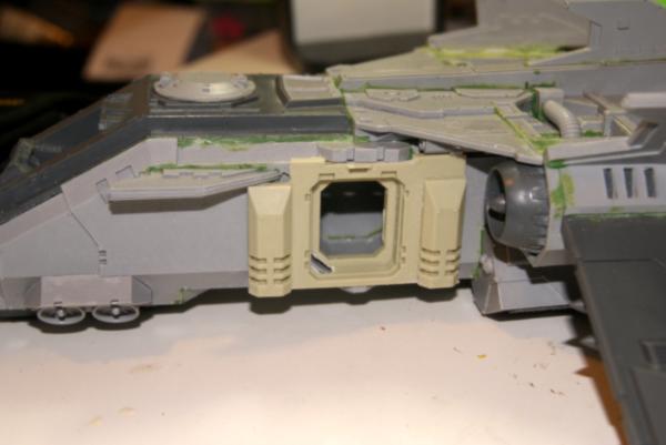
These are important because this is the space that the storm eagle missile launchers will live if I can get that to all work out. (I'm feeling pretty confident at the moment.) So I dry fit the vents.
Then I bored a 1/8" hole in the vents, and in the dorsal plate of the flyer to throw some magnets into. When I do my magnets, I like to counter bore one magnet so it is depressed, then the second magnet is proud and slots into the bored hole as well as having the magnet holding it. However, this is best achieved by through drilling with a very tiny bit of glue holding it in place. If you can't through drill, then it is better to put the magnet/magnets flush with the surface.
A quick size comparison of vents vs rocket pods. However, holding them in place on the vent pad, it will work fine.
Rocket pods time! I found some rocket pods and ordered them, but since it will be forever for them to get here, I used the ones I had laying around.
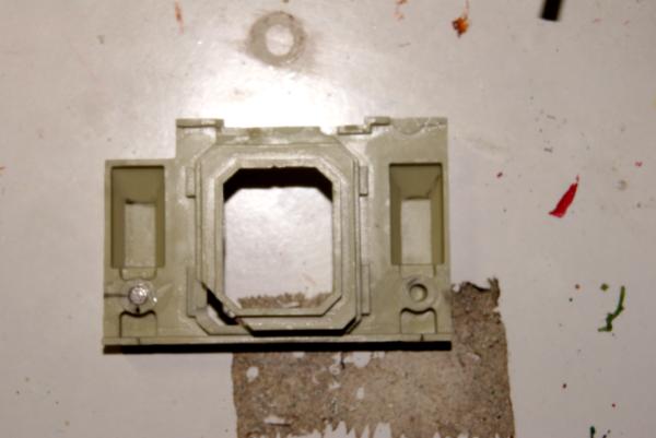
The difference in mounting is there is a double bracket for the storm eagle, and a single box for the raptor. Easy to fix. Green stuff I summon thee! I put some stuff holes in the back of the two supports and then filled the space in with green stuff. I extended the supports as well, making a rectangle just a little bigger then the one on the raptors dorsal plate.
The two rocket pods got greened up together, and then I let them sit for about an hour.
The reason I let them sit was to get the green stuff base tacky and slightly harder, but not so it wouldn't mix when I added a skirt to it. This is what would go around the form on the raptor. I put a good bit of water on the raptor back, press and use some tools to square against, and voila, it's a mold of the place they will go.
The process of compressing the new supports flared them out a touch which will get squared off once it is all dry.
So I used my scalpel to square off the sides of the rocket pod base. I then cross marked the magnet in the dorsal plate and extended lines well out. These then were transferred to the rocket pod bases. 1/8 X 1/8 magnets were plenty of grip, so a quick drill later and voila.
A touch of clean up, and paint and those are done. Easiest part of the quick conversion....Check!
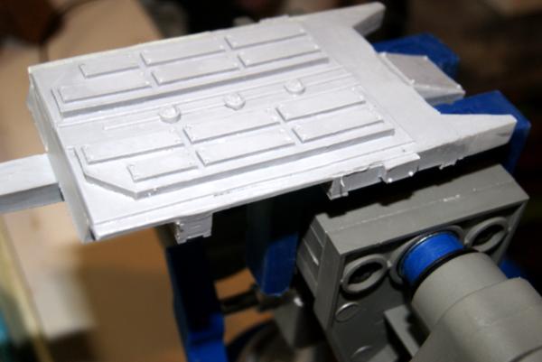
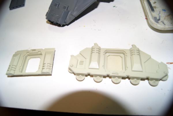
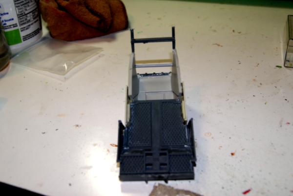
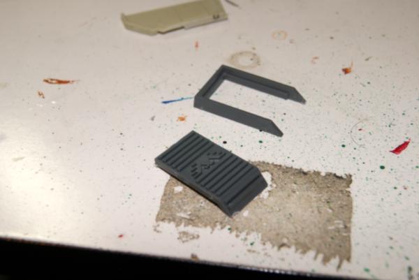
Next is the forward assault hatch. Easily the toughest part. I've been debating pieces of vehicle siding and parts with hatches in them as bases to start my construction of the facade. The imperial stuff I had was just kind of...meh. Then I had an epiphany today. The land raider assault ramp was originally based off of the wave serpent hatches! (grumble, but eldar can't assault out of them, grumble, grumble.) So I looked around and sure enough I had the back end of a wave serpent sitting to the side, and with a quick fit we find.....
The shape fits almost perffectly!
This also will set up well with the storm raven floor plate that comes with the kit. It all extends into a storm eagle facade complete with stepped assault ramps. I trimmed about a 1/4" off of the wave serpent at the top. This brought the whole thing a touch closer to the hull and is about the minimum that I need to get a good looking bow door. I then found that the steps at the "forward" edge of the wave serpent fit perfectly into the storm raven decking.
Ad glue, and voila!
While that was drying I started digging around for how I would complete the bow door. I have an internal door for a land raider, and it seems to fit the same as the assault ramp door.
Except they are the same, instead of the synced up piece. I'll see if I can come up with the other door and be golden.
Continuing the assault door, I'm doing my best to use mostly parts that are easy to order via bitz sites or included in the kit. So Here I have the rear plate of the storm raven that comes with the kit. I'm cutting around the edges of the landing gear, and transferred up to just under the tail insert.
I primarily used a scalpel for the cutting, but once I had gotten through most of the plastic at the top and sides, I used some nippers to cut the more reinforced lower lip.
The edges are still rough, but they are going to be smoothed and green stuffed to match the wave serpent troop sectional. I will also trim the wave serpent interior of the hatch to match the assault ramp.
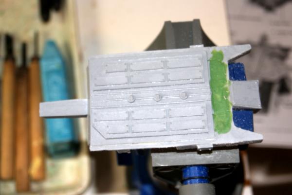
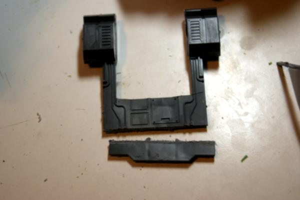
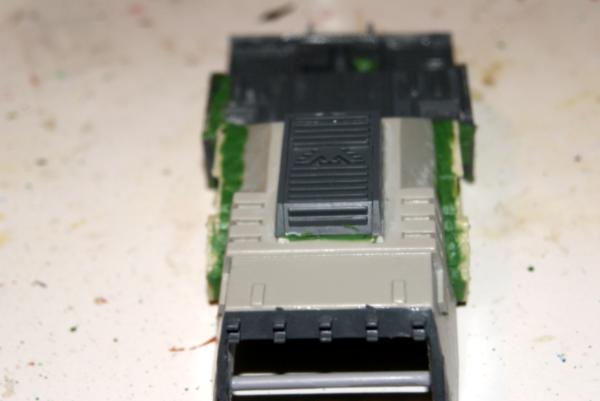
Stepping aside from the bow hatch for a moment, I'm attacking the side hatches. A rhino side chassis works perfectly I think. I have found when working with trimmed pieces of other vehicles, turn it upside down. Once upside down it is hard to recognize. So after trimming the ends of the rhino chassis straight from the smoke stacks. I trim the stack tops off. Square all with a file.
I removed the stand offs on the inside of what will now be the port side hatch. I also cut out a section above the forward reinforcement. Cutting out the notched piece at what is now the top fits almost perfectly around the upper light bracket. Now that the port hatch is roughly in place I'm doing the minor trimming to make it fit.
Taking it slow from the front I found a spot on the bottom of the bow fin. I marked with a pen, then very carefully notched it out. A touch of the file and it fits pretty well. I did the same nipping out just the forward corner where the hatch fits around that upper light bracket.
I want to place the magnets at the four corners at least, to help the piece suck up smooth to the outer hull of the chassis. The first magnet was pretty obvious, being placed in the hole at the forward lower corner. The aft one when I marked it against the hull was sadly right where the first depth change to the door is, so I will have to block out and put a new hole there. I also transferred marks for the forward one where the magnet did fit in.
I also marked the border of the storm eagle replacement hatch, and then double checked the marks, glad I did as I found them off slightly. I checked a third time and it matched, so install magnet.
As I had noted with the aft lower hole being unusable, I blocked them out as well as blocking out portions at the top corners where I wanted to place the additional magnets. One magnet and the tight fit already holds the piece in place, so four should help keep any warping from being visible.
Doors from the storm raven kit fit perfectly as they are the same as rhino hatches. This precludes the need to really seal up the cutout section from fitting to the chassis.
There were a number of gaps around the side hatches where the straight sides of the rhino doors were a touch overhanging on the 45 degree angle for the flyer chassis. I wanted to make these as tight a fit as I was able, so I used plastic sheeting from my green stuff, laid that between the hull adn the rhino door. Then created a nice big green stuff halo and pressed it ala molding form.
While this was all drying, I went back into the crew compartment and bow hatch. I removed a section of the stern from the storm raven to make the after most portion of the crew compartment.
I then notched it to fit around the bottom of the chassis.
This has now given me a consistent point where that butts against the two side light sections. Using some tail plates from the storm raven and some parts from the front portion of the rhino that I chopped apart I have created a port and starboard side to the crew compartment. Concerned about the strength of the shape being maintained a the bow. I decided to add some sprue reinforcements.
Continuing to make the wave serpent hatch look less eldar and more Imperial, I am adding the new landing pad. This was also available in the storm raven parts. Although it needed a touch of filing, and a tang removal. This fit on the slides under the wave serpent compartment very well.
The rear quarter of the rhino sections I have been using I glued together. These will form the aft section of the crew compartment where the wave serpent section meets the Imperial section.
I marked and trimmed the top portion of the section off so it fits kind of like this.
Now I have the larger sections of siding and the parts from the rhino at least dry fit, and some attached it is about time to throw some greenstuff on there.
It is time to add the magnets. So I placed holes for four magnets in the bottom of the flyer. There are already the two magnets for the bolt cannons in the front. There is space for two more right at the bow if I need to utilize them.
Next on the docket is adding the green stuff to fill in the spaces left by the paneling on the crew compartment. I just squared off the angles that were already there. Once I have the final panel in the back where the wave serpent meets the Imperial decking, I will have this space nearly done.
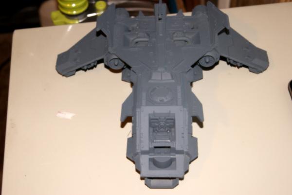
With most of the work completed on the customization, I am ready to prime the whole thing! I will do the final fitting of the crew hatch when the pilot and cockpit are all painted and sealed up.
Final sectional:
Spoiler:
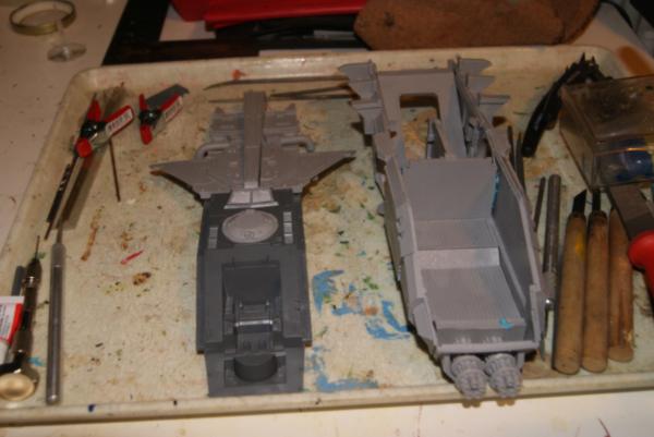
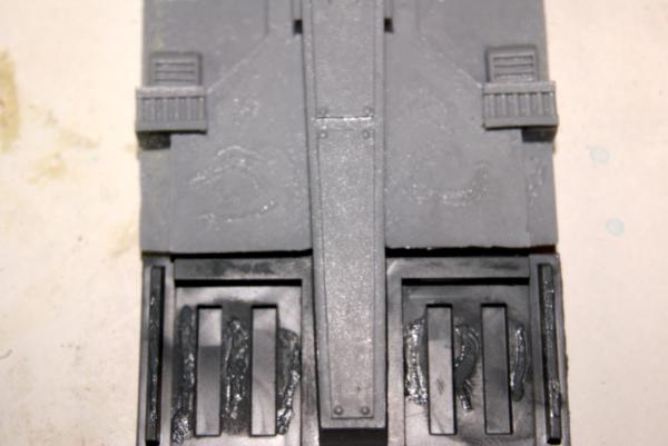
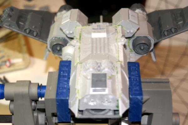
What's this! Primed bits! Off to the client this evening and I thought I would deliver him some parts. He can paint the marine and cockpit cover, and have some detail work he can do.
More priming! That looks pretty sweet if I do say so myself.
This message was edited 31 times. Last update was at 2016/04/09 02:31:47
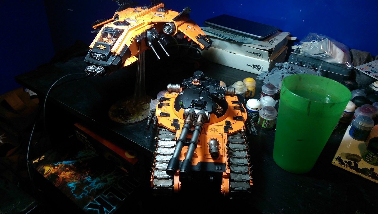
I really feel like there should be model complexity numbers for some of the kits that forgeworld and GW put out. Thinking back to the 1-6 range from building model boats and such. The storm eagle/fire raptor are really tough. The sicarian battle tank on the other hand is a pretty good, simple construction with solid casting.
It makes me concerned about their new storm bird kit that is bigger then a thunder hawk, but based off the style of the storm eagle.
I'm interested to build my chinese re-cast storm eagle in the near future. See if that comes out any better.
It is possible to assemble the fire raptor and the storm raven without doing all this work. You will still likely need to hot water treat the four panels, but you don't have to get them perfectly flat. You can assemble it completely without using any green stuff. When you paint it, a lot of the blemishes go away, and you can turn miscast offsets into weathering or battle damage.
When I assemble a model, I just like to build it as I would a wooden boat. I take the time and care to make sure that it is assembled to the best of my abilities.
I was thinking about magnetizing them when I get to it. I haven't started assembling the ball turrets. I was also at one point trying to figure out if/how I could magnetize the front of the flyer so it could be swapped into a storm eagle.
I'm still hopeful I will come up with an epiphany, but I don't think it likely for the storm eagle swap, but magnetizing the weapons should be easy enough.
Depends upon the surface. I've added pins or green stuff holes for all of the larger sections. Especially where there is stress from a natural bend in the resin.
Pinning:
I pin in narrow connection points or when something sticks far out. Example:
When I was not going to magnetize the bolt cannons, I pinned them. Where sides of the chassis fit into the deck, or upper plate of the flyer, I pinned where it naturally held off.
I think of pinning as a way to increase the surface area of what I am gluing, so I use it where the surface area available is insufficient to make a good bond.
Green stuff holes:
When doing large flat surfaces like the engine body to the wing hull. Especially with resin, these large surfaces tend to be either concave or convex, the liquid as it sets into resin tends to do this based on it's process of cooling down. It's difficult to pin a large section like this accurately, where making things true (lined up fore and aft) and level (lined up horizontally or at 90 degrees.) The pin hole gets misaligned and either your piece is off, or you have to bore out the hole and thus lose much of the support you were going for. The hole that you then put a touch of glue into just before you have the green stuff connect creates that larger surface area bond, and has the flexibility when you first put it together to be tweaked into the perfect place.
General green stuff work:
I often come back to the attachment points that I have put together with big square kits like this, because edges end up rounded, or gaps appear because you are making the angles match as you want. I do not consider this green stuff to be adhering or structural, it's more like the paste you put over a hole in the wall. Any additional stability that I get out of what is cosmetic work, is a bonus. Where that doesn't hold true, is when I put super glue on a surface, then green stuff, then super glue. Then attach the next piece. This sandwich style around the green stuff makes it a structural bonding process.
Super glue:
Personally I like the Scotch brand gel super glue. It's a little more expensive, but I find I can work with it better, and I don't get it on my hands as often. I also am using zap a gap super glue for this model, and it has a pretty good fine application nozzle, although I have to clean it semi-regularly.
Epoxy:
Epoxy with resin you have to be careful with. The materials are very similar and I've had epoxy (which takes forever to set in the modeling world timeline.) Sometimes the catalyst for 3M epoxy, and for west systems epoxy can over harden your resin, or melt it if you apply too much of the base. (softening a mix that has already partially set.) this is especially a concern with the Chinese re-cast stuff. It's still off gassing and kicking for a month after I receive it. (Alternately I drilled into one of the engine chassis for this project and found a pocket of un-mixed, still liquid resin from the forgeworld kit.)
I would only use epoxy in an extreme gap filling circumstance. (Bigger then the 1/8" gaps I had here.) Where I needed to shape and reattach a fragile piece, and it would only work resin to resin. (Plastic is how you mask off epoxy projects.)
Hope that answers your questions, but if not, shoot me more.
Thanks for the rundown. I'll have to check out the 3M brand superglue. My experience with some super glues is that there is some shelf life. The joins 'dry out' at some point, become even more brittle and eventually break.


 work?
work?

