6825
Post by: The_Blackadder
I'm really over my head on this one. Scale will make or break this model and I can't get any decent leg measurements from the photos.
I'm trying a different approach this time as I think the titan will be too top heavy if I make it all from plastic and resin. I'll begin with a basic hull shape as thats what I'm most sure of as far as scale. I've put about a week of evenings into this so far and I'm about to start on the head.
I'm using foam filled poster board 5mm and 13mm thick which works very well and will give me the upper body lightness I'll be needing for stability. The body will be covered with sheet styrene after I get all the proportions right.
I'm thinking 3/4" pine square stock for the leg segments and dowels for the round joints but that may be to massive when covered with styrene.
The Blackadder
5
6825
Post by: The_Blackadder
No responses to my rather tawdry effort thus far and I'm not surprised give the mediocrity of the images. I put a few hours in last week and this is how the model stands at the moment.
The Blackadder
5
9910
Post by: CommissarKhaine
Hi there Blackadder, looks, like a nice start. I really like your tanks as well. If you need measurements, try finding some templates on the net. I don't have them myself, but I'm sure some helpful soul here can direct you to a proper site.
MOst scratchbuilds I've seen so far are either cardboard or plasticard, and don't seem too top-heavy. Guess the foot design must be pretty decent  .
116
Post by: Waaagh_Gonads
The_Blackadder wrote:I'm really over my head on this one. Scale will make or break this model and I can't get any decent leg measurements from the photos.
*Cough*
To scale Lucius Pattern Warhound Plans
4th post down.
http://www.dakkadakka.com/dakkaforum/posts/list/3840/99366.page
*Cough*
6825
Post by: The_Blackadder
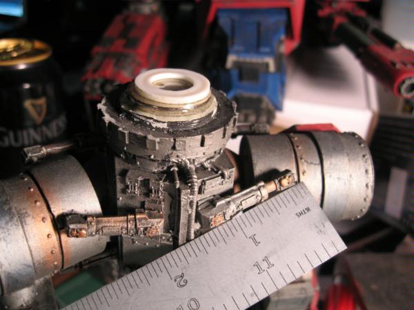
Thanks, I really appreciate the input. I had those plans already and based on my calculations they are approximately 1/4 oversized when it comes to the length and cross section of the legs. The 3/4 view DWG 119 at the end when roughly modeled in wood gave me an overall height of 10.5 inches which is FW's claim for the height with the legs fully extended. I can always bulk up the segments with plastic card sheets if need be and increase the length likewise if the legs look too small. unless someone can give me measurements off of the original model.
My calculations based on the FW assembly instructions give me give me slightly over 3/4 inch square leg segments in cross section with each leg piece approx. 3 inches long. Anyhow below is the work of the previous day and I am rather pleased at the outcome if the scale is correct.
EB
3
10694
Post by: jamunition
wow its going to tern out really good
6825
Post by: The_Blackadder
Thanks for the reply jamunition.
I've just completed the leg joints (of course everything is rough because I'm not sure with the scale.) but the leg joints are fully movable so when the model is assembled I can pose it as I want. I'm hoping to leave it posable so that was my main concern with weight. The pistons and hydraulic cylinders will be the fly in the ointment as they will have to extend and contract as the legs are adjusted. This may not be practical but hey why not give it a go. Otherwise I'll just pose it as I want, glue it in position and then add the hyd. cylinder's etc.
I'm using white styrene 1/2 inch tubing for the joints and naturally the joints are in excess of 5/8 inch diameter so I have to build them up with 3 layers of 1/2 inch tubing and filling in the gaps as 1/2 inch styrene is the largest diameter available to me. Fortunately the 7/16 inch tubing fits into the 1/2inch nice and snug so it makes an ideal axle for the joint. The grey assembly pegs sticking out of the joints are bits of GW model sprue and careful aligning and paring down of these pegs give a nice tight fit to the leg components so the adjustment has significant strength when moved.
Onward and upward,
The Blackadder
5
10915
Post by: chaos_inar
hey i reckon this is cool but i reckon the legs are a bit dainty or skinny kinda both
8551
Post by: captain.gordino
That would be because they don't have the armour on them yet, I assume. If you look at FW ones the actual legs are pretty scrawny, they just have big plates on them.
6825
Post by: The_Blackadder
chaos_inar wrote:hey i reckon this is cool but i reckon the legs are a bit dainty or skinny kinda both
The legs where they are square in cross section will be getting a covering of thin sheet styrene the thickness depending on how the three segments look when assembled. This is in addition to the leg armor. (Thanks for the input Capt.Gordino) The cylinderical portion of the ankle section appears to be right but I can always add another layer to thicken them up. I'm pretty sure I have the cylindrical joints nailed as far as diameter but I just discovered I was mistaken in the length of both the middle (calf) and upper (thigh) length and will have to shorten them, the middle significantly. This will subtract from the overall height estimate and I sure would like to know if the FW 10.5 inch height spec is based on the legs fully extended as straight as they can be assembled? My model when jury rigged together just makes 10.5" but looks weird as hell with the legs straight. LOL I'm going to pick up about an eighth of an inch when the feet are assembled and another eighth when I adjust the height of the waist component. I really appreciate the input as I am just guessing at th dimensions right now. What I really need is a few actual dimensions off of the original. Fortunately, nothing I've done cannot be amended without rebuilding the part but I hope to have the legs completed by Friday. All input is welcome, Thanks, EB More pictures later today
6825
Post by: The_Blackadder
captain.gordino wrote:That would be because they don't have the armour on them yet, I assume. If you look at FW ones the actual legs are pretty scrawny, they just have big plates on them.
Thanks for the input Capt.Gordino,
The legs where they are square in cross section will be getting a covering of thin sheet styrene the thickness depending on how the three segments look when assembled. This will hide the seams of the substructure and flesh out the legs for a more robust look.
This is in addition to the leg armour as you so correctly pointed out.
All comments and criticisms are welcome because my goal is to have an exact replica when finished.
The not at all innovative on this one, Blackadder
10101
Post by: kharndude
looks pretty good for a wip
6825
Post by: The_Blackadder
The_Blackadder wrote:chaos_inar wrote:hey i reckon this is cool but i reckon the legs are a bit dainty or skinny kinda both
The legs where they are square in cross section will be getting a covering of thin sheet styrene the thickness depending on how the three segments look when assembled. This is in addition to the leg armor. (Thanks for the input Capt.Gordino)
The cylinderical portion of the ankle section appears to be right but I can always add another layer to thicken them up.
I'm pretty sure I have the cylindrical joints nailed as far as diameter but I just discovered I was mistaken in the length of both the middle (calf) and upper (thigh) length and will have to shorten them, the middle significantly.
This will subtract from the overall height estimate and I sure would like to know if the FW 10.5 inch height spec is based on the legs fully extended as straight as they can be assembled? My model when jury rigged together just makes 10.5" but looks weird as hell with the legs straight. LOL
I'm going to pick up about an eighth of an inch when the feet are assembled and another eighth when I adjust the height of the waist component.
I really appreciate the input as I am just guessing at th dimensions right now. What I really need is a few actual dimensions off of the original. Fortunately, nothing I've done cannot be amended without rebuilding the part but I hope to have the legs completed by Friday.
All input is welcome,
Well I can't say I wasn't told, 'Chaos_inar' said the legs looked skrawny and d---ed if he wasn't right. I just recalculated all the components and I'm lacking mm's in almost all measurements. This would be so much easier if some kind soul that actually has a Warhound would fain to give me a few vital dimensions. Not that any of the work done so far is completely wasted, it's just a matter of gluing on some more sheet styrene. The joints are scrap as there is no way I can beef them up to the proper dimension. Fortunately PVC tubing comes in the request size. Yes, I'm in the realm where a plumbing supply is my hobby store LOL
The Blackadder
6825
Post by: The_Blackadder
It's been quite some time since I last addressed this thread. I've been quite busy the economy being what it is but I have made some progress on my (sons) Warhound.
When last I showed it I was apprised the legs were too delicate looking for the body. Absolutely correct and I scrapped 90% of the work I had done on the legs. Fortunately the new dimensions brought me up to the PVC pipe range which made the joints easier to fabricate. I kept the hull and covered it with .05" plastic sheeting. There is a commercial 7 minute epoxy made for plastic and it is wonderful stuff. It even adheres plastic to card stock.
I'll go into greater detail of the construction but first a picture to see if my effort meets your approval.
Blackadder
1
6825
Post by: The_Blackadder
A few more images:
2
12358
Post by: StubbyGB
To be honest it currently looks like a top heavy chicken ,BUT ! so does the original. Ive only got a couple of Epic scale Warhounds for ref, but I think once you get the armour plating on the lower legs they will look much better.
It looks like you are doing a great job with this, I wish I was as brave as you to start a project like this and had half the skill needed to see it through 
keep the pics coming, its looking good so far.
11516
Post by: deadly chicken
looks great!
what weapons are you going to arm it with?
6825
Post by: The_Blackadder
StubbyGB wrote:To be honest it currently looks like a top heavy chicken ,BUT ! so does the original. Ive only got a couple of Epic scale Warhounds for ref, but I think once you get the armour plating on the lower legs they will look much better. It looks like you are doing a great job with this, I wish I was as brave as you to start a project like this and had half the skill needed to see it through keep the pics coming, its looking good so far.
Thanks for the candid input.; it looks like that to me as well. Now that I have an assembled set of legs and waist with the hull attached I superimposed my model on a side view of FW legs. The overall scale is correct but the hip cylinders are about a quarter of an inch small in diameter and likewise the ball mounted waist connection. The upper knee joint needs to be repositioned a quarter inch lower in the shank. deadly chicken wrote:What weapons are you giong to arm it with?
eventually it will have a full complement of weapons but first will be the bolter and lascannons which are the easiest to fabricate. I've already made a plasma cannon for my Titan Hunter http://www.dakkadakka.com/dakkaforum/posts/list/30/210995.page#503153 so other than the tedium of making another it is the best looking weapon and to round out the ensemble the flame thrower which has a low priorty on my list. They will of course be quick change mounted and movable. Thanks for the replies, Blackadder
5
12463
Post by: cadium
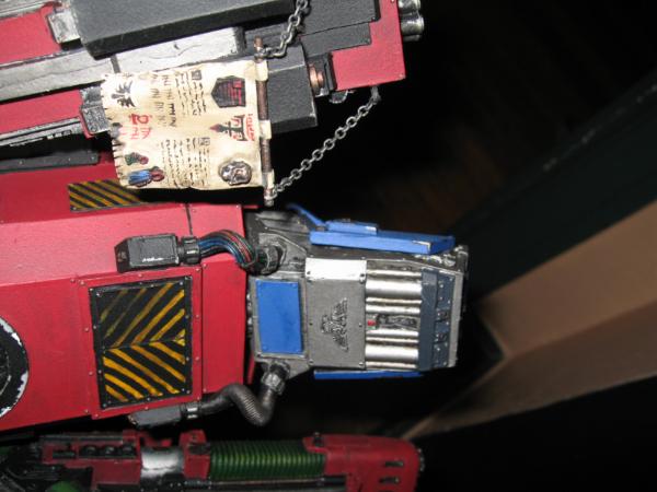
Well done! this looks absolutely, stonkingly, brilliant. I know how demanding scratch builds can be. As for the moving hydraulics, these are not too difficult. The outer tube and rod both need a pivot at the end and this is achieved with a pin (either styrene or brass) through the rod and through the piston securing tabs. make sure the hole through the rod is just big enough to allow the pin to rotate. Also leave the rod long enough so that it wont pop out at full extension. Hopefully this diagram may explain it better than words.
1
8551
Post by: captain.gordino
Looks like it will be cool. I look forward to further updates.
6825
Post by: The_Blackadder
Finally the rear view which may not be the exact dimensions of the original as I made the generator housings a bit wider than FW on purpose. To my eye they look better and eliminate the gap between the generators and the top hull ventilating housing which I'm sure was done on the original model for assembly purposes; mine are faired into the vent housing which is more esthically pleasing IMHO.
The bottom view show the arms bays are still not covered with plastic card. You may also note that the right and left carapaces do not taper to the front as in the original FW Lucius Warhound. That was a choice I purposely made; I didn't like how it looked the other way.
Blackadder
2
9217
Post by: KingCracker
I love titan builds. You titan builders man the Ork in me get excited. Nice work so far!!
6825
Post by: The_Blackadder
One picture is worth a thousand words and in this case a thousand errors of perception. Working without any plan or measurement I have made numerous errors in scale and one digital photo revealed them. So after an all night rebuild here is the result plus I managed to attach the head as well. Incidentally all the leg and hip joints including the feet and toes are fully movable and posable at this point and I made the neck connection movable as well. Try that one FW 
Whew,
E. Blackadder
Constructive critiques and comments would be greatly appreciated,
EB
11516
Post by: deadly chicken
wow that kicks ork ass.
do you have any templates or a list of materials so I can make one 2.
I doubt it will be anywhere near as good as that 1 though
6825
Post by: The_Blackadder
deadly chicken wrote:wow that kicks ork ass.
do you have any templates or a list of materials so I can make one 2.
I doubt it will be anywhere near as good as that 1 though
I can give you a list of material and plan to give a step by step construction in future posts but I haven't so much as a single measurement or template to offer. everything I have done so far is by trial and error and redoing over and over until it looks right (to me). I have asked numerous times for measurements on many forums and received none although M. Silva was gracious enough to offer them in a PM, I missed that when I was taking a break from building.
I've made a lot of mistakes that I worked out so anyone attemption to duplicate this model won't have to repeat and for some foolish reason I spent a lot of time making the model fully posable which is probably a waste as once the pistons and cylinders are installed the range of motion will be severely limited even with ' Cadium's' thoughtful input.
The real fun part is ahead in the detailing of this model; the part I enjoy the most. All the basic structure assembly is behind me so the model as you see it is about as good as it going to be IMHO unless someone can point out some grievious flaw.
E. Blackadder
6825
Post by: The_Blackadder
Regarding the above comment by me; I just mounted the head to the body today and I may have placed it a quarter inch too high on the neck so I'm aware of that discrepancy TYVM
I'll go into how I mounted the head and neck to allow full movement which could be accomplished on a FW model if anyone is interested
EB
9505
Post by: CaptainRavenclaw
I think its great. I really hope this isn't a grievious flaw...but when the weapons are on is it going to be too front heavy? I'd hate to see it fall face first onto the battlefield.
Hope it balances well. It looks great!
6825
Post by: The_Blackadder
s.j.mccartney wrote:I think its great. I really hope this isn't a grievious flaw...but when the weapons are on is it going to be too front heavy? I'd hate to see it fall face first onto the battlefield.
Hope it balances well. It looks great!
I've already made plans to drill half inch holes in the screen generator housings (The bottom of course) and fill them with half inch lead rods as needed after the weapons and details are added. I also am going to move the pivot shaft forward a quarter inch, at the moment it is only tacked in with epoxy. The entire hull, carapace, and head cores are made of foam filled poster board covered with .5mm sheet styrene and only weighs a couple of ' ounces' not pounds as the FW resin model must weigh. Thanks for the input, EB
6825
Post by: The_Blackadder
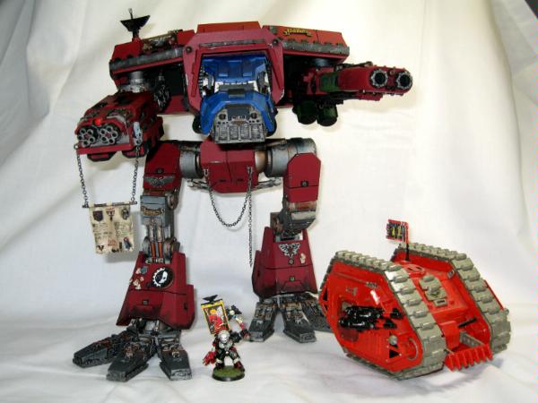
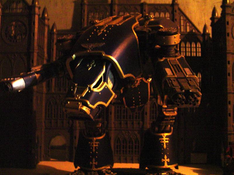
You know just when you think you have really nailed a hobby and are feelly good about the results of your efforts something comes along that puts you in your place. Take a look at what I found on the net. This d---ed thing stands 28" high and is so detailed as to make my warhound look like a cardboard box. This model is so incredibly detailed that at first I thought it was an artists painting. What a fantastic model!!! I have more images if anyone else doesn't feel inadequate enough. Blackadder
2764
Post by: AgeOfEgos
The_Blackadder wrote:You know just when you think you have really nailed a hobby and are feelly good about the results of your efforts something comes along that puts you in your place. Take a look at what I found on the net. This d---ed thing stands 28" high and is so detailed as to make my warhound look like a cardboard box. This model is so incredibly detailed that at first I thought it was an artists painting.
What a fantastic model!!!
I have more images if anyone else doesn't feel inadequate enough.
Blackadder
Wow, what's the source URL for that?
/I used to think I was good at a few things, then I found the internet.
6825
Post by: The_Blackadder
Heres another picture to ruminate on while I search for the link.
I call this one "The last thing Blackadder saw before being squashed like a bug.
9505
Post by: CaptainRavenclaw
wow. where did you get that?
518
Post by: Kid_Kyoto
yeah, I stared at that for 5 minutes trying to figure out if it was a screen capture or a model.
It's real!
6825
Post by: The_Blackadder
Kid_Kyoto wrote:yeah, I stared at that for 5 minutes trying to figure out if it was a screen capture or a model.
It's real!
Oh it's real alright and I have some building photos to prove it. I've read the rules here several times and see nothing about posting links to another site but rather than break any rules, I'll just feed the images.
I took the liberty to increase the size of the images for better viewing. The construction images are only 300X250.
Heres a few building shots. All that are posted on the site thus far:
4
12048
Post by: punkisntdeadyet
wow. the warlord titan is my personal favourite recreation of the Epic Model in 40k scale. I applaud your skills sir!
11292
Post by: Druidic
You know, the one thing I can never fathom, camoflage on an 80 ft behemoth..... just an observation. :-)
12471
Post by: Buttlerthepug
The_Blackadder wrote:You know just when you think you have really nailed a hobby and are feelly good about the results of your efforts something comes along that puts you in your place. Take a look at what I found on the net. This d---ed thing stands 28" high and is so detailed as to make my warhound look like a cardboard box. This model is so incredibly detailed that at first I thought it was an artists painting.
What a fantastic model!!!
I have more images if anyone else doesn't feel inadequate enough.
Blackadder
HAHAHA!!! i am so happy to see that model on the net... it was made by someone at my local games workshop battle bunker and is now on display there... it was one of the most fun things ive ever gotten to fite!
12897
Post by: gutmaximus
head on over to belloflostsouls blogspot website.. the builder has provided a brief article on the build... simply fantastic...
10345
Post by: LunaHound
This has detailed WIP parts:

11292
Post by: Druidic
Feth me...... And here was me planning a small Apoc Knight project..... feel everso slightly humbled!
6825
Post by: The_Blackadder
Most scratch titans larger than the oft replicated Warhound very often look like a cannibalised vacuum cleaners painted like carnival floats. This Warlord actually looks like it actually has a place on the battlefield. As for the camouflage I agree, unless you paint it to look like Mount Everest camouflage is superfluous but I suppose it has to be painted some color so at least it is in keeping with the rest of the battle group. I like the camoflage theme in this case; kind of looks like clouds.
At any rate I'm awestruck by the sheer majesty of the thing.
After I get done with my piddlin' Warhound, I know what my next project will be. 
Blackadder
12212
Post by: Lord Kaesar II
now that is one serious killer titan. and i dig the WIP shots with the people on the weapons' walking spaces. puts you in your place then. just wow
10892
Post by: Emrab
THATS THE COOLEST THING EVER! ITS GLORIOUS!
I'm shocked. It does not look real even tough it is.
8529
Post by: MuffinButt358
My god... whether we're talking about the titan you're making or the pictures of the various other ones you've put up, it makes me jealous and puts everything I've done to shame.
13165
Post by: xabian
wow fantastic works, i guess the next stop is life size right =P
10203
Post by: lolzman
could we see a scale please
12562
Post by: Captain_Cow
That is freakin' awsome...
excellent work so far buddy
9393
Post by: Zaku I
Heh, When I saw these pictures, Panzermensch kicked on. Heh I can totally picture these heavy metal f-ers walking all over the board like 'Imma stomp you!' I just found my newest project...that will most likely end like the others one a quater finished. Say think you could send me a link to this big guy? I would love to see more, and keep up the good work on your titans...
4003
Post by: Nurglitch
That Warlord Titan is a thing of beauty. The textures and plates on its hull really make it work: no large blank areas that scream "I'm a deodorant bottle!"
I hope someone designs a Lucius pattern Imperator Titan like that someday...
7416
Post by: jabbakahut
Saw this on BoLS and nearly cried, incredible work.
7899
Post by: The Dreadnote
Now that's what I call a titan!
9788
Post by: goffnob deffsmakka
I want to loot that.
9505
Post by: CaptainRavenclaw
I do want one. But where can a mere mortal store one of those behemoths? My house just isn't big enough, I'll have to build another wing onto my house before I can store it!
6825
Post by: The_Blackadder
Druidic wrote:You know, the one thing I can never fathom, camoflage on an 80 ft behemoth..... just an observation. :-)
Lets see, a Warhound is approximately 50 feet tall I suppose that is standing still with the legs at a neutral bent angle. and the model is 10.5 inches. Now the modeler of the Warlord Titan David Smith states his model is 28 inches tall which calculates into 133.33 feet tall life size. granted not an item for a book shelf but an addition to the house shouldn't be necessary unless you live in a trailer park.
EB
12212
Post by: Lord Kaesar II
nice calculations, which would leave me at the general understanding that if mine is a the intimidating 30 inches, then it should be approx. 150 feet rl?
11810
Post by: the assasin of night
well you hav taken on a hell of a task and you deserve a medal for that and then considering how well it terned out you deserve a gold medal
6825
Post by: The_Blackadder
I get the feeling that people are crediting me with the Warlord Titan. That fantastic item is the work of David Smith on a site called Bell of lost souls.
mine is the comparatively diminutive Lucius Warhound which at the moment is enough on my plate for the forseeable future although my son is already checking out prices on a Epic Warlord for me to scale up. I just was facinated by the beauty of a project extremely well executed and used my thread to bring it to your awareness.
E. Blackadder
7899
Post by: The Dreadnote
Lord Kaesar II wrote:nice calculations, which would leave me at the general understanding that if mine is a the intimidating 30 inches, then it should be approx. 150 feet rl?
I make it about 130. IA 3 puts the height of a warhound at 14 metres, or 0.75 metres IRL to an inch of model size. So 30 inches would be 40 metres, or about 130 feet.
Not that any of this should be taken as gospel mind you, just another estimate
12212
Post by: Lord Kaesar II
if a warlord can be agreed upon to be ~30 inches in 40k format, then how many inches might an imperator be? i know it's somewhat off topic, but it just came to mind
12471
Post by: Buttlerthepug
well the one david smith made was not the 36" high warlord that EVERYONE assumes.... he based it off epic scales models and made it as much bigger then a warhound in 40k scale as in epic... i know... i fought it... and it is amazing o_o
7766
Post by: Anti-Mag
Kudos on that guy making a titan look like a true weapon of war. Detail, colouring and weathering are unmatched from nearly all of the titan threads on here. Compelling to see a vison completed with such flair and clarity. Thanks for sharing it here.
Yours is coming along nicely too!
5636
Post by: warpcrafter
Your work is true quality. Can't wait to see it painted.
6825
Post by: The_Blackadder
A rather disheartened Blackadder here after finding that prodigious Warlord Titan posted. I mean a Warhound project just doesn't seem all that big a deal anymore.
But I'm still plugging away because I still like the look of a Lucius Wolf class hound.
Today I've finally gotten the cockpit window frames and windshield frame installed. I'll install the windows after it's painted. I also have the head swivel mechanism nailed down and I'm fairly sure my head to body proportions are pretty close to correct.
I disassembled the neck to show how I made the swivel. It just plugs into the hull orifice and I probably won't glue it as the fit is quite tight.
I used a discarded paint roller tube for the sleeve and ground down a pvc pipe fitting for the gimbal housing. A 1.250 inch dia. wooden drawer knob is the orbit sphere and the front and back race is 1.0 pvc pipe beveled down for the ball to seat against.
A lot of trouble I know but it bothers me that the FW model can't be posed for different battle situations. Just about everything on my model can be moved and I managed to keep to the scale.
So here are today's images, I hope you enjoy seeing them as much as I do posting them.
E. Blackadder
13250
Post by: Lord of battles
lets see more pictures
6825
Post by: The_Blackadder
I found another picture of that d---ed Warlord
1
9505
Post by: CaptainRavenclaw
It is a beast. And the skills you're learning by making your warhound will help you make that beast!
7899
Post by: The Dreadnote
Lord Kaesar II wrote:if a warlord can be agreed upon to be ~30 inches in 40k format, then how many inches might an imperator be? i know it's somewhat off topic, but it just came to mind
I'm gonna take a brief moment to plug this topic.
Warhound's looking good, Blackadder! How long would you say you are from completion?
13085
Post by: jackinthetank
The_Blackadder wrote:I found another picture of that d---ed Warlord
That's one hell of a titan!
6825
Post by: The_Blackadder
s.j.mccartney wrote:It is a beast. And the skills you're learning by making your warhound will help you make that beast!
I admire your optimism. The Dreadnote wrote:Lord Kaesar II wrote:if a warlord can be agreed upon to be ~30 inches in 40k format, then how many inches might an imperator be? i know it's somewhat off topic, but it just came to mind
I'm gonna take a brief moment to plug this topic. Warhound's looking good, Blackadder! How long would you say you are from completion?
Thanks for the encouragement. I'm just beginning the fun part (the detail) now that I am satisfied with the overall dimensions. I started installing the radiator??? and the nose cowl and head armor today and hope to post a picture later this evening. There's a tremendous amount of minute detail to make this thing look right and even though I opted for the easiest weapons I'm figuring completion some time in the summer. Now I have to figure out the summer of which year. Blackadder
6825
Post by: The_Blackadder
warpcrafter wrote:Your work is true quality. Can't wait to see it painted.
I have decided on a paint scheme one that looks like it would belong on a battle field I'm sorry to say given my penchant for drab coloring
Below is how I want it to look when completed.
Lottsa Luck Blackadder.
1
7416
Post by: jabbakahut
I like the muted coloring, but it needs more metal on it. Any place that moves cannot have paint on it, it would be worn off.
On mine I may have gone too far the other way with a lot of metal areas, I think a good idea would be to compromise between the two.
6825
Post by: The_Blackadder
jabbakahut wrote:I like the muted coloring, but it needs more metal on it. Any place that moves cannot have paint on it, it would be worn off. On mine I may have gone too far the other way with a lot of metal areas, I think a good idea would be to compromise between the two.
Well thats just drop dead gorgeous. Too pretty to shoot bullets at. If my son had his way the one I'm building probably would be red as well but as I told him, "You can paint the one you build any color you want or repaint this one when I drop dead.  " Thanks for the images, I can always use more reference material. The still working in the dark, Blackadder
6825
Post by: The_Blackadder
jabbakahut wrote:I like the muted coloring, but it needs more metal on it. Any place that moves cannot have paint on it, it would be worn off.
On mine I may have gone too far the other way with a lot of metal areas, I think a good idea would be to compromise between the two.
Damn me Sir! those are the pictures I've been looking for. Any chance of posting them in that size downloadable???
and a picture of the underside of the head would be a real blessing.
Thanks in anticipation,
Blackadder
12853
Post by: Breaker
jabbakahut wrote:
So when I saw that I immediatly thought "Since when did Optimus Prime start working for the emperor?" anyways back on topic.
Good stuff so far, looks fantastic. Can't wait for the weapon pics to start showing up, any thoughts on how your gonna kit this bad boy out?
9504
Post by: sonofruss
Well this one is not a Lucius patt it is still kool.
8927
Post by: Salted Diamond
Breaker wrote:jabbakahut wrote:
So when I saw that I immediatly thought "Since when did Optimus Prime start working for the emperor?" anyways back on topic.
Good stuff so far, looks fantastic. Can't wait for the weapon pics to start showing up, any thoughts on how your gonna kit this bad boy out?
I had the exact same thought about that paint scheme. Good thing his legs aren't blue or the resemblance to Optimus Prime would be too much.
7416
Post by: jabbakahut
The_Blackadder wrote:Thanks for the images, I can always use more reference material.
The still working in the dark, Blackadder
If you look in my sig block, there is a link to a book on how to build one (of the FW, not scratch). You can view the PDF of download it with a free account. I've also uploaded more misc images to my Titan Gallery.
6825
Post by: The_Blackadder
jabbakahut wrote:The_Blackadder wrote:Thanks for the images, I can always use more reference material.
The still working in the dark, Blackadder
If you look in my sig block, there is a link to a book on how to build one (of the FW, not scratch). You can view the PDF of download it with a free account. I've also uploaded more misc images to my Titan Gallery.
I just downloaded the building guide you posted on 'Scribd'. What an invaluable assistance it will provide in my future construction. Thank you very much. I'm sorry to see you never got the toe issue resolved properly I can offer some assistance on refabricating FW mistakes. With a razor saw the toe could be cut down to the proper length and width and with careful cutting the side and bottom detail can be excised and re-attached. I use Met-all 24 hr epoxy when refabricating resin parts. and Locktite 7 minute epoxy for assembling Resin and plastic scratchbuilt models. I actually had the tail booms on my FW Vulture two different lengths by over 3/8 inch! and I had to fabricate a cockpit canopy for a ' FW Chaos Viper'. FW has never seen fit to even get back to me for that replacement. Back to the manual, I see that the waist component I fabricated is a bit too small which I already knew and the orbit and sphere is also approx 1/8 inch diameter too small according to my calculations. It's a pity that in your marvelous manual you never included a 6 inch scale for reference sizes but why would you as the manual is for building a FW product not a ripoff. There are a few tantalizing partial glimpses of the bottom of the head of the Warhound in your manual. If someone could post a picture of that I would be very grateful. Thanks again, Blackadder
6825
Post by: The_Blackadder
The_Blackadder wrote:
Back to the manual, I see that the waist component I fabricated is a bit too small which I already knew and the orbit and sphere is also approx 1/8 inch diameter too small according to my calculations. It's a pity that in your marvelous manual you never included a 6 inch scale for reference sizes but why would you as the manual is for building a FW product not a ripoff. :
Damn me I must be blind, the blue work mat in your manual has crosshatch squares on it. Could you inform me as to the size of those squares? centimeters or inches?
Thanks,
E. B.
1
9217
Post by: KingCracker
Well it looks like its really coming along! Good work so far. And good luck as well
7416
Post by: jabbakahut
The_Blackadder wrote:It's a pity that in your marvelous manual you never included a 6 inch scale for reference sizes but why would you as the manual is for building a FW product not a ripoff.
Great point, I will be sure to include that in my Reaver manual.
7416
Post by: jabbakahut
The_Blackadder wrote:
Damn me I must be blind, the blue work mat in your manual has crosshatch squares on it. Could you inform me as to the size of those squares? centimeters or inches?
Thanks,
E. B.
They're 1 inch squares.
And thanks for the comment on the guide, it's actually over 4000 views. Although for some reason the tracker information went from inticating an average of 5 views a day to none! I don't know, whatever. As long as it can help someone. Cheer!
6825
Post by: The_Blackadder
jabbakahut wrote:
They're 1 inch squares.
And thanks for the comment on the guide, it's actually over 4000 views. Although for some reason the tracker information went from inticating an average of 5 views a day to none! I don't know, whatever. As long as it can help someone. Cheer!
My inaccuracy in typing is only exceeded by my poor proofreading ability. 4000 is what I intended.
1 inch squares, then the toes are dead on but the foot base is a tad too small. I also didn't undercut the front of the foot base so adding a bit to the front and rear should remedy both discrepancies. Your manual is already paying dividends. With your permission I'm going to recommend it on all the other sites I visit. Warhammer 40k that is.
Blackadder
Still hoping for that underside view of the Warhound head
E.B.
7416
Post by: jabbakahut
The_Blackadder wrote:jabbakahut wrote:
They're 1 inch squares.
And thanks for the comment on the guide, it's actually over 4000 views. Although for some reason the tracker information went from inticating an average of 5 views a day to none! I don't know, whatever. As long as it can help someone. Cheer!
My inaccuracy in typing is only exceeded by my poor proofreading ability. 4000 is what I intended.
1 inch squares, then the toes are dead on but the foot base is a tad too small. I also didn't undercut the front of the foot base so adding a bit to the front and rear should remedy both discrepancies. Your manual is already paying dividends. With your permission I'm going to recommend it on all the other sites I visit. Warhammer 40k that is.
Blackadder
Still hoping for that underside view of the Warhound head
E.B.
I'll break it out and take some photo's in the morning, any other requests?
7416
Post by: jabbakahut
Okay, I added 4 more pics to my titan gallery. And don't forget to click on them, you can zoom in for any detail you need.
6825
Post by: The_Blackadder
Whoa, be careful what you wish for. First of all Thanks Jabba for the outstanding images of the bottom of the head (for want of a better word). I had no idea there was so much detail on the underside.
There's a few discrepancies in my version but not enough to change what I have. Right now the head armor is a bit too thin. and the angle of the fore to aft run of the base footprint is not extreme enough but it will have to do as you can see by the posted image of this dates work the armor is in place.
Onward and upward as they say.
Thanks again,
Blackadder
5
12212
Post by: Lord Kaesar II
legs look kinda scrawny without armour, but otherwise it's looking very good so far
7416
Post by: jabbakahut
I totally understand when you nitpick your own work, but I think it looks really good anyway.
6825
Post by: The_Blackadder
Lord Kaesar II wrote:legs look kinda scrawny without armour, but otherwise it's looking very good so far
The tubular section of the shank of the legs are approximately 1/4 inch too long I believe. I'll cut them down (as they are still removable) when I add the detail to the shanks. each round shank tube gets rings of reinforcement an 1/8th inch thick and a sleeve between them that will flesh them out significantly. The ankle piston/cylinders will also add bulk to the overall appearance even with out the armor ankle skirts. The square blocks of the hip and knees that the joints connect to are 1 inch square in cross section (according to my guesstimations) and superimpose on the images of an actual Warhound almost exactly. I know about the foot pad body being 1/4 inch too short in length and when I detail the feet I'll remedy that. Thanks for the input I need that to keep me on my toes, EB Below is an image demonstrating the way the shanks are attached to the ankle joint block. the X in cross section stem presses into the shank tube rather tightly so the feet will always be removable for repair and modification as necessary. This image also give a good demonstration of how flexible the leg and toe joints are. each leg and the toes are capable of a full range of motion and after I get the model completed and painted I'll address the oversized toe joint cylinders. they're approx 1/16 inch too large in diameter Best guesstimation. I'll make caps to close the holes in the toe joints but I'm thinking of casting them as I need 26 and even I wouldn't be up to making 26 of anything!!! The really long tube sticking out of the waist fits into the body pivot sleeve and allow the body to rotate 360 degrees on the waist. It's tapered and a close tolerance press fit so again it shouldn't ever need to be glued in place.
3
6825
Post by: The_Blackadder
jabbakahut wrote:I totally understand when you nitpick your own work, but I think it looks really good anyway.
Thanks, but if I start compromising on the basic structure it will weigh on my mind until I correct it or I will lose interest in completing the project altogether if it's seriously flawed ( that's happened before on a few of my endeavors). I just put the whole thing on back burner until I work up the ambition to do it right which could be never.
A chilling glimpse into the Blackadder's psyche.
11754
Post by: ojk9
IMO the legs are too thin/long/both - looks like a crow.
(And so do the feet, actually - try making them thicker maybe?)
9505
Post by: CaptainRavenclaw
I think it'll balance out a lot more when it has armour and guns on it. Don't forget, its a scout titan, its meant to be agile!!
Keep up your awesome progress. I love it!
6825
Post by: The_Blackadder
ojk9 wrote:IMO the legs are too thin/long/both - looks like a crow.
(And so do the feet, actually - try making them thicker maybe?)
So much for the British penchant for reserved, staid understatement. While I appreciate your candor we'll just have to wait and see if my seat of the pants perceptions are too far off target. As for the feet, as I stated before and were verified by Jabba's work mat dimensions they're very close to perfect. Once the hydraulics, geegaws, and treads are installed they should look thicker. Whew, I was reading your reply and at first I thought you said, "It looks like a cow!" A 'crow' I can live with. Blackadder It's all a matter of perspective, here's a shot of a Warhound where the body looks way too small for the legs and this is a production model
2
11810
Post by: the assasin of night
bet it will look even more impresive when you get it completily painted
10339
Post by: tallmantim
Great work - I like the look of it.
Keep going, keep going!
12585
Post by: zachwho
awesome man!! keep it up
11186
Post by: Masaioh
Another awesome scratchbuilt warhound.
BTW, does anyone know what guns that warlord was equipped with? And is there a picture I could look for that shows what all the titan weapons look like?
12212
Post by: Lord Kaesar II
for the arms, the warlord has a plasma destructor, volcano cannon, quake cannon, laser blaster, melta cannon, gatling blaster, and close combat weapon.
for the shoulders it has the apocalypse missile launcher, a vortex missile, the duble-barrelled turbo blaster, plasma blastgun, inferno gun, and vulcan megabolter.
however, note that it's not all of them, but just 2 for each area. sorry, but i have no pictures on hand, but there's no definitive answer on the weapons: it's up to you
7416
Post by: jabbakahut
There is this website called Forge World which may be helpful.
12504
Post by: Exarch_Nektel
iT LOOKS LIKE IT'LL COME TOGETHER QUITE NICELY, NICE JOB.
Damned warp spawn of a caps lock.
13640
Post by: Ranger4x4
I would just like to say that your Warhound is epic.
12358
Post by: StubbyGB
you know I was just thinking about camouflage on these things, and I remember someone asking why try to hide something this big ?
Well check this out :-
http://www.shipcamouflage.com/warship_camouflage.htm
It must be worthwhile or they wouldn't do it.
Personally I think camo / muted titans just look cool. Have two Epic scale Warhounds painted very dark Grey, they look menacing even at that scale.
6825
Post by: The_Blackadder
StubbyGB wrote:you know I was just thinking about camouflage on these things, and I remember someone asking why try to hide something this big ?
Well check this out :-
http://www.shipcamouflage.com/warship_camouflage.htm
It must be worthwhile or they wouldn't do it.
Personally I think camo / muted titans just look cool. Have two Epic scale Warhounds painted very dark Grey, they look menacing even at that scale.
Ya know, I had that conversation with my son because we both were aware of the North Atlantic fleets using camouflage in WWII. The reason for that was to disguise the true size of the ship for fooling reconnaissance; Some ships had a false bow wave ( can't remember which ones). Due to the choppy and cloudy nature of the N. Atlantic, such tactics could be marginally effective before the advent of decent radar. The Bismark and the Price Eugen were frequently confused during the hunt for the Bismark due to the similarity of the camouflage and how it served to break up the profile in stormy weather but probably no one didn't know they were there. In the days before radar directed gunfire anything to confuse the gunnery observer was useful. According to some Naval websites I've been on the camoflage usually had the reverse effect and sometimes enhance the ship instead of obscuring it
Quote:
"The dark grey stern and bow was (sic) to shorten the ships length and thus its size, but later tests and studies on ship camouflage conducted by Kapitänleutnant Dechend in 1942 showed, that dark areas of ships accented these parts of the ship rather than concealing them when viewed from a distance. After these studies bows and sterns were painted light grey or white-grey to shorten the ships length. This worked fine (e.g. Tirpitz, Scharnhorst, etc.)."
In the main it was to break up the silhouette not to hide altogether. After the advent of radar very few fleets resorted to camouflage.
One would expect that 38k from now the radar should be at least as effective as it is today so camouflage would be only so much decoration much as painting your tank red ala Blood Angels.
JOAO,
Blackadder
6825
Post by: The_Blackadder
I'm really quite insane you know; based on the underside of the head images provided by Jabba I found out why the muzzle of the beast did not look quite right to me. There are subtle angles not apparent in the images I found on the net and from FW but were revealed in those provided by Jabba. Anyhow I totally sanded off the front of the nose and started over and right now the newly replaced sheathing is drying. then I need to replace the headlight bezels and the grill strips and we're back to where I was a few days ago but hopefully with a better facade more in keeping with a Wolf class Warhound.
Now if I can only find a straight jacket that allows freedom of motion for my hands I'll be back in business.
Conveying messages via the guard in this ward at Bedlam,
Blackadder
"They called me mad, and I called them mad, and damn them, they outvoted me."
Quote: playwright Nathaniel Lee
6825
Post by: The_Blackadder
I managed to put a little detail on the head today after the major rebuild of the muzzle yesterday. Once I am satisfied with the overall appearance the fine detail should go a lot faster. Right now I am sourcing the fans that go into the grill on the back between the carapaces. I've seen them before but I don't remember where. Any input would be appreciated.
7
6825
Post by: The_Blackadder
Whoops, forgot the last picture.
The fan housing on the back.
2
7416
Post by: jabbakahut
I would do the fans one of two ways, go to a hobby store and looks for a vehicle which has wheel rims that will work. If you get some Fast & Furious looking model, it should have something that will work. Otherwise take any rim-fill it with green stuff and cut the blades into it. I thought there might be something on the baneblade sprues, but a quick look doesn't show anything.
6568
Post by: Azmodai
Brilliant scratch build of a Warhound, way better than my simple one...
There is a part from Cities of Death with a nice fan on, I've made a cast of it and used on my knight. (see the team anarchy thread in my signature...)
Azmo
10912
Post by: BOSS_PIMPALOTZ
Nice!
7416
Post by: jabbakahut
Azmodai wrote:Brilliant scratch build of a Warhound, way better than my simple one...
There is a part from Cities of Death with a nice fan on, I've made a cast of it and used on my knight. (see the team anarchy thread in my signature...)
Azmo

I don't see the bits you're talking about.
7416
Post by: jabbakahut
jabbakahut wrote:Azmodai wrote:Brilliant scratch build of a Warhound, way better than my simple one...
There is a part from Cities of Death with a nice fan on, I've made a cast of it and used on my knight. (see the team anarchy thread in my signature...)
Azmo
I don't see the bits you're talking about.
EDIT: I think I see what you're talking about, the fan on his bum? I like that idea of molding that, good idea.
6568
Post by: Azmodai
Yeah, the one on his bum
Azmo
9910
Post by: CommissarKhaine
Fans can be found on the COD Manufactorum sprues. I also believe the vindicator's top plate might be a suitable candidate:

6568
Post by: Azmodai
CommissarKhaine wrote:Fans can be found on the COD Manufactorum sprues. I also believe the vindicator's top plate might be a suitable candidate:
Even better fans!!!
Hmmm, think I'll buy those... For some future project, like a better Thunderbolt
Azmo
6825
Post by: The_Blackadder
In a bit of a hurry today but I took some pictures over the weekend of the progress thusfar.
More to come later this evening,
Blackadder
1
3564
Post by: Brother Bartius
The legs wont look so scrawny once the leg armour is on, trust me.
This looks great for a scratch build. Nice attention to detail.
6568
Post by: Azmodai
Will be hard to tell that one and a FW one apart when painted...
Azmo
6825
Post by: The_Blackadder
Thanks for the words of encouragement. I started this project attempting to build a Warhound facsimile for my son out of foam filled board but the more I got into it the more I wanted to have a realistic copy of the original. I have departed from the original design in a few areas especially the shield generator housings in the back which looked a bit small and blocky on the original. Mine are larger and I think more in keeping with the overall sleekness of the rest of the model; the carapace at least.
I'm not too worried about the legs any more; I believe they are within a millimeter of accuracy in diameter and length. my major concern is the hip ball joints which are 3mm too small in diameter although it's hard to see the difference. I've left the waist for last in detailing as I still am looking for a ball 2.57cm in diameter.
Below are the images of the model to date:
once again thanks for the replies and input,
E. Blackadder
10
7416
Post by: jabbakahut
Insane, I would put money on not being able to pick this one out of a FW line up, the underside detail is incredible.
8551
Post by: captain.gordino
Now That is the kind of detail I like. This is s brilliant job. Keep at this, it might be the best warhound scratchbuild I've seen yet.
6825
Post by: The_Blackadder
jabbakahut wrote:Insane, I would put money on not being able to pick this one out of a FW line up, the underside detail is incredible.
More underside detail. Thanks for the kind words, but: Purists will note that I departed from the original in the aux servo compartments albeit through necessity as my carapace ceiling is over 1.3cm thick. this is because originally I used 1/2 foam core poster board as it was to be a trial build for practice. It came out so well I just decided to skin it in sheet styrene and let it go at that forgetting the extra thick ceiling; whoops. Came the time to add the detail and lo and behold there was not enough recess depth for the actual compartment components. Even I drew the line at completely rebuilding the carapace so hence my amended version. Sue me for laziness but at this point I just want to see the d---ed thing done, Blackadder
2
6825
Post by: The_Blackadder
jabbakahut wrote:Insane, I would put money on not being able to pick this one out of a FW line up, the underside detail is incredible.
Jabba I just noticed the above response was from you. I want to express my appreciation for your excellent documentation which was instrumental in the degree of detail I have achieved; I couldn't have done it without your assistance.
Blackadder
7416
Post by: jabbakahut
No problem, my pleasure. I see what you mean by the thickness of the carapace now. Luckily it's near undetectable when viewed from the top (gaming view).
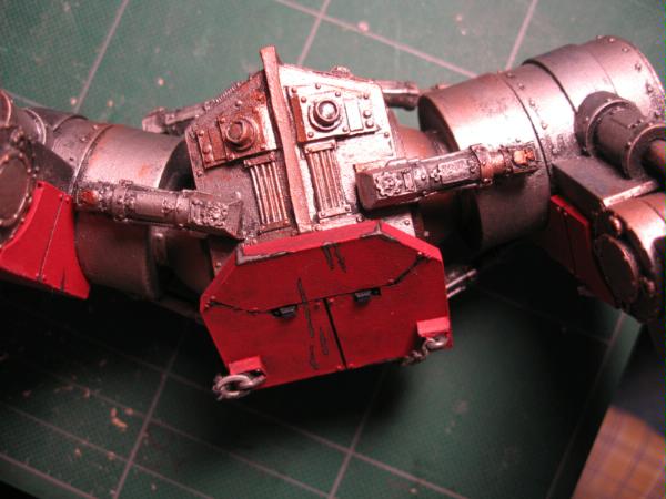
6825
Post by: The_Blackadder
Thanks to all for the words of encouragement. I've been agonising over the following step and trying to figure out how to make a proper ring of plastic around the orbit of the ankle and hip ball socket receptacle and the following is how I finally managed to accomplish it. 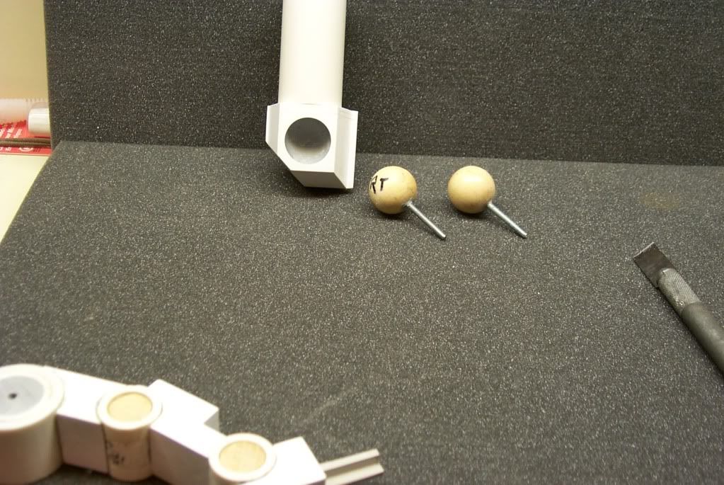 Surprisingly simplicity itself but the most obvious somehow escapes us. I started by gluing with a good grade of thin liquid plastic glue. I use 'Tamiya - Extra Thin Cement : 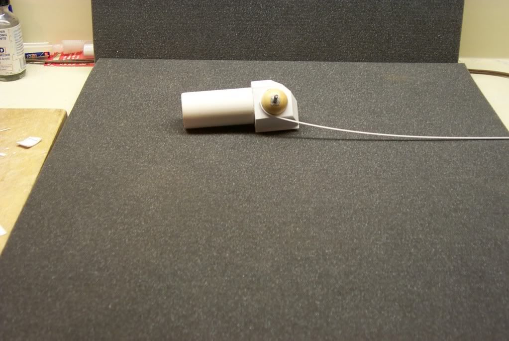 I glued the selected piece to the periphery of the socket using the installed ball as an inner guide. fortunately I used wooden spheres so they are not affected by the glue. I imparted a slight curve to the ring strip initially and started a bit before the desired location so the beginning end could be cut off leaving a curved beginning. 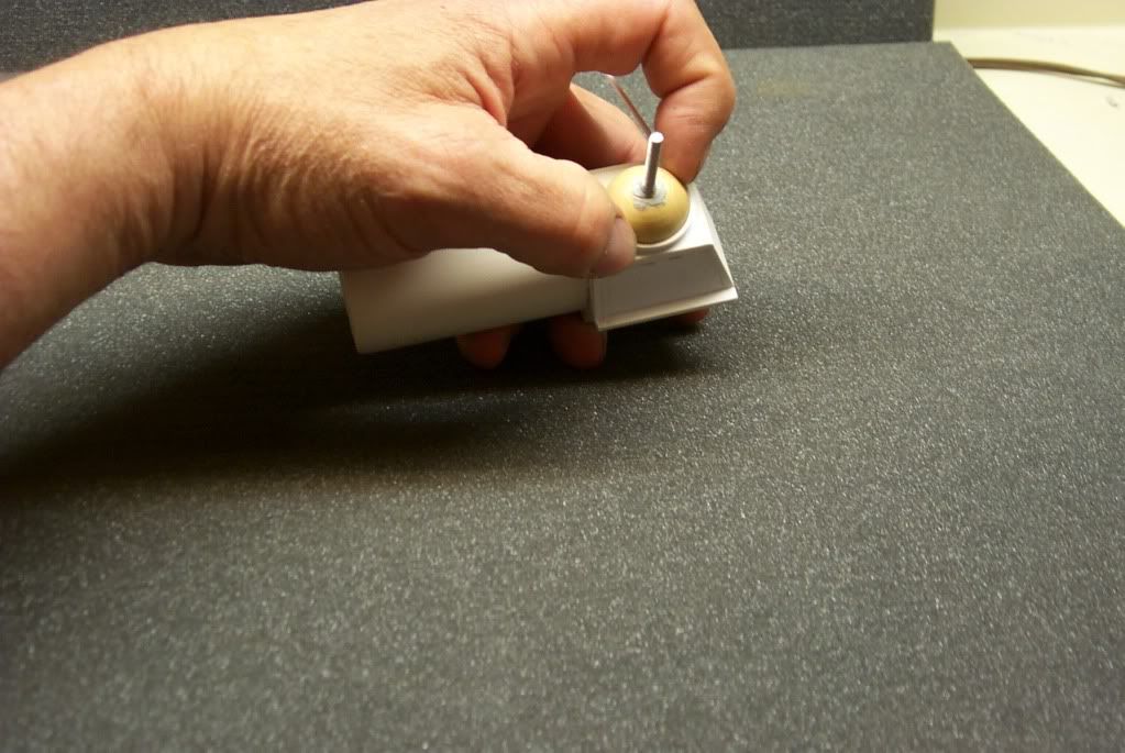 Applying pressure with your thumb (or favorite finger) serves two purposes; one it is a clamp you can rely on to make the proper curve and two the heat of your hand speed the drying of the glue. 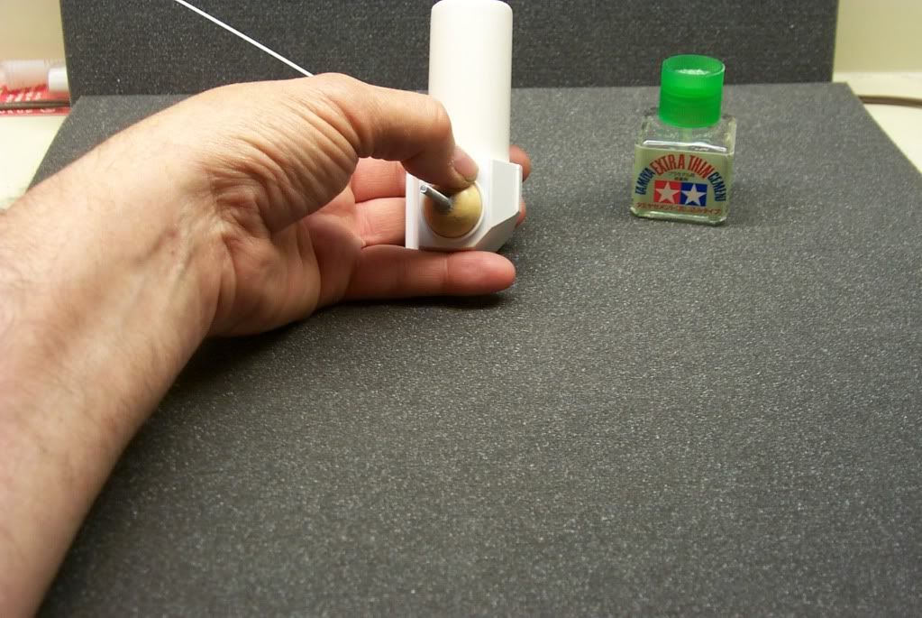 Following the curve of the ball make gluing every 30 degrees or so being careful to not let the glue flow back to the starting point as it may dissolve the original joint and you'll have to start over. 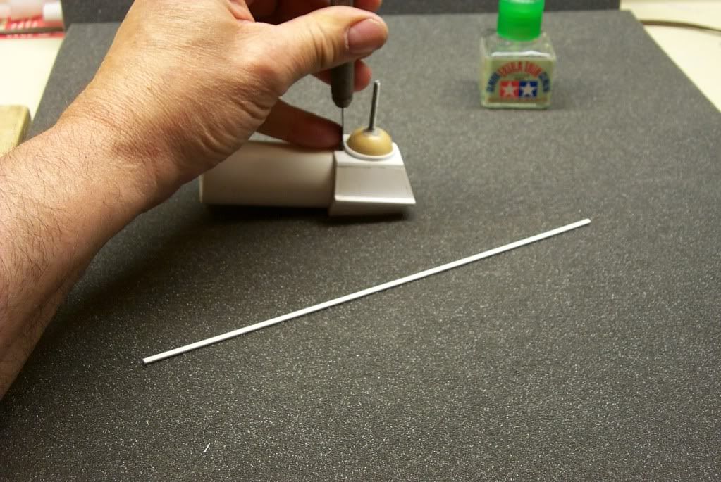 working your way around the ball to the starting point, cut off the short straight piece from the beginning and cut the end of the strip to butt with the beginning and voila; a perfect ring of plastic. 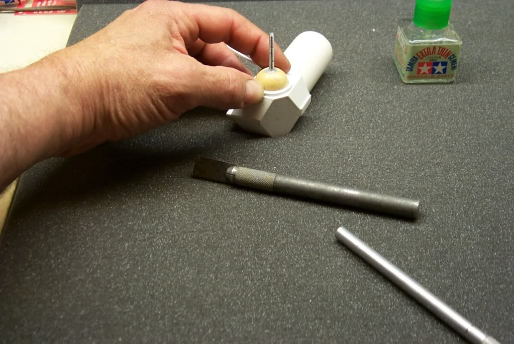 I needed a second ring to thicken the ring on the ankle and hip but the second layer is easier than the first and my only complaint is why didn't I think of this sooner. The mentally challenged Blackadder
7416
Post by: jabbakahut
Pretty good. I'm curious how you manage to cut all the details you've made as cleanly as they look, are most of your cuts just several passes of an exato?
10339
Post by: tallmantim
Looking great Blackadder!
It all looks incredibly professional.
13017
Post by: littleboyblues
Awsome attention to detail. Most scratch builds lack that extra detail to make them A+ models.
6825
Post by: The_Blackadder
jabbakahut wrote:Pretty good. I'm curious how you manage to cut all the details you've made as cleanly as they look, are most of your cuts just several passes of an exato?
I rarely use an exacto for straight cuts; the blades are too hard to control for a long straight cut. I use my experience cutting drywall (I'm a do it yourselfer) to follow a pencil line with a standard Stanley or General utility knife which has an edge as sharp as an exacto but the size and heft to give great control. This is the knife I use almost exclusively: http://content.costco.com/Images/Content/Product/725979b.jpg You can really bear down on the blade and a cut to a depth of 1/8" is not too difficult with practice. I usually make two passes; the first to scribe a groove to follow. Once you've made a cut you can snap the sheet for a clean break. Occasionally I dress the cut with a Craftsman or Nicholson 'flat smooth' file. I use a #11 blade to carve out rounded detail and cleanup work and the 1/2 inch chisel blade to shave pieces. I also used these blades to scrap scratches from plastic after they have lost their tips. http://www.pcbsupplies.com/catalog/Xacto%20Knife%2011%20M%20Blade.jpg Another tool I find indespensible is the deep bladed exacto razor saw although I never use the mitre box which I think is a waste of money. http://www2.gpmd.com/image/x/xacr1435.jpg EB
7416
Post by: jabbakahut
Forbidden
You don't have permission to access /image/x/xacr1435.jpg on this server.
I use my mind box all the time, but then again I'm working on building buildings-a lot of 45 cuts on those.
8724
Post by: faolan
The_Blackadder wrote:Thanks for the words of encouragement. I started this project attempting to build a Warhound facsimile for my son out of foam filled board but the more I got into it the more I wanted to have a realistic copy of the original. I have departed from the original design in a few areas especially the shield generator housings in the back which looked a bit small and blocky on the original. Mine are larger and I think more in keeping with the overall sleekness of the rest of the model; the carapace at least.
I have to say, I've been following your plog for a bit, but never commented because (cringe, don't kill me) I changed browsers and forgot what my login was for, oh, a couple of months.
This looks more and more splendid every time I come back and look, BAdder.
As to the above quote... can I be your son, too? I promise to bring ya home beer once in a while and cook your steaks just right!
I'm late with it I know, but for engines/fan intakes, one can always try http://www.evilmushroomgames.com/. My pal Tom's used them before for his Aquila lander and perhaps even his otherwise scratchbuilt Thunderbolt(s).
6825
Post by: The_Blackadder
jabbakahut wrote:Forbidden
You don't have permission to access /image/x/xacr1435.jpg on this server.
I use my mind box all the time, but then again I'm working on building buildings-a lot of 45 cuts on those.
The slots in the mitre box are so much wider than the razor saw blade that the cut very likely will be on an angle other than 90 in depth plus you are limited to what, 4.5cm in length of cut. I'd rather trust my eye and hand to make those cuts besides by practicing freehand cutting you will quickly gain the skills to eliminate all but the most basic tools. I have a battery power Dremel, belt sander and a Craftsman hobby scroll saw and very rarely use them.
14956
Post by: Muoio 117
Sorry I haven't posted anything previous to this. All I've got to say is this is AWESOME!!! This is the best scratchbuilt warhound I've every seen. Good job. You've inspired me to build my own warhound.
One question though. What size (thickness) sheet styrene did you use to cover the torso's base of foam?
6825
Post by: The_Blackadder
Muoio 117 wrote:Sorry I haven't posted anything previous to this. All I've got to say is this is AWESOME!!! This is the best scratchbuilt warhound I've every seen. Good job. You've inspired me to build my own warhound.
One question though. What size (thickness) sheet styrene did you use to cover the torso's base of foam?
Thanks for the accolades.
The thickness depends on whether I intend to sand or cut detail into the surface. I usually use 1.0 mm stock to cover the foam board. In areas where I'm afraid I'll exceed the scale I use 0.5mm or less.
I would be greatly interested in coaching you in your build effort offering what help I can if you need it. Please don't hesitate to ask anything. The big problem is getting accurate measurements of the various critical parts. Studing Jabba's Manual will help you immensely. I wish I had it during the initial building.
Right now I am working on the leg hydraulics and detail. I hope to have some images tomorrow.
EB
9505
Post by: CaptainRavenclaw
Keep it coming blackadder, this thread is a great inspiration. If I ever get around to scratch building a warhound (which I really want to but time is too busy) I want to build two simultaniously. Would you recommend it? It'd mean more cost and hours, but less in the long term.
6825
Post by: The_Blackadder
s.j.mccartney wrote:Keep it coming blackadder, this thread is a great inspiration. If I ever get around to scratch building a warhound (which I really want to but time is too busy) I want to build two simultaniously. Would you recommend it? It'd mean more cost and hours, but less in the long term.
Funny you should mention that as I was just thinking of building two Warlord titans simultaneously after this project. One to sell on Ebay if I could actually bring myself to part with it. The problem is; repetition is my bane. The tedium of making 16 Warhound toes and 20 ankle hydraulic cylinders not to mention the toe hydraulics (Egad I forgot about those! Fah!) 64 teeny tiny bits of telescoping plastic!!! I've got to figure a way around that.
Many times when I was building the toes I just felt like forgetting the whole thing.
If I had the patience for repetition I would have taken up knitting,
The easily bored Blackadder
6825
Post by: The_Blackadder
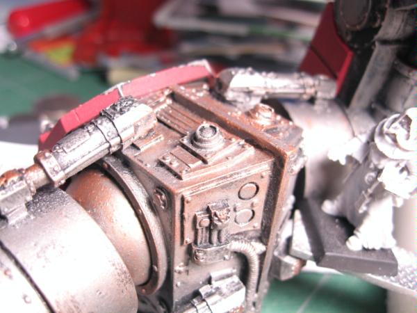
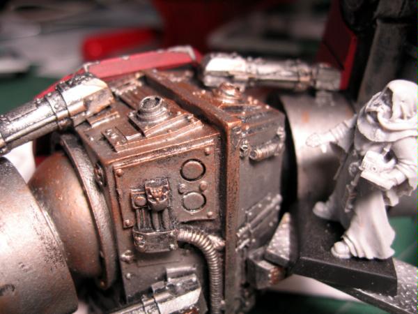
Whew, it's been a week or so since I posted some progress images. I managed to solve the problem of the ankle articulation so I could have telescoping hydraulic cylinders. I had to do extensive cutting of the lower leg segment and ankle joint to accommodate the piston and cylinder bases. The fine detail of the cylinder reinforcement rings have demonstrated to me that there is a limit to how much tinier I can go in the medium of styrene plastic. putting rivet detail on those rings is seemingly out of the question as the filing dust is not much smaller than the rivets themselves. even the cylinder data plates which I made of 0.25mm sheet styrene appear too thick and will have to be sanded thinner.
The cylinder base hinge points I just took a guess at and fortunately I guessed correctly. The cyl. range of motion is minimal e.g. on the order of 0.5mm to 1.0mm. The piston base has a larger range of motion; approximately 2.0mm to 3.0mm as the joint is flexed. All in all the pistons have a travel of about 0.5cm which is sufficient for most poses of the leg as any further extention begins to look rather silly. I consider these cylinders the hardest to make due to the enclosed nature of the housings so the hip cylinders will be a cinch relatively speaking.
EB
5
11516
Post by: deadly chicken
your lucky!
My cutting about the same class of that of a highly spasticated slow on drugs!
8724
Post by: faolan
For the super thin bits like that, why not use a 3x5 card?
Thicker than writing paper, thinner than most plasticard.
6825
Post by: The_Blackadder
faolan wrote:For the super thin bits like that, why not use a 3x5 card?
Thicker than writing paper, thinner than most plasticard.
The strips I use are actually thinner than file cards at 0.25mm plus compatible with super thin plastic glue. Thanks for the input, EB
6825
Post by: The_Blackadder
The full range of motion upper and lower leg hydraulics installed albeit without the finally dressing, cleaning and fine detail (note the pins instead of proper axles for quick disassembly. Still a work in progress and the unforgiving eye of the camera disclosed some troubling flaws in the squareness of my cuts that were not readily apparent to my bleary eyes. 
11330
Post by: Gundam-Mecha
Great work Blackadder! The plasticard detailing is spot on. I own a Mars pattern Warhound from FW myself, and I must say looking at those pictures of the scratch built feet you'd be hard pressed to tell the difference.
It's a real pleasure to see such a high quality scratch build project.
6825
Post by: The_Blackadder
Gundam-Mecha wrote:Great work Blackadder! The plasticard detailing is spot on. I own a Mars pattern Warhound from FW myself, and I must say looking at those pictures of the scratch built feet you'd be hard pressed to tell the difference.
It's a real pleasure to see such a high quality scratch build project.
Thanks for the compliment. The feet have been a source of concern to me since I obtained more detailed information. Working from the limited FW building guide and grainy images I managed to get the feet to an acceptible quality but the excellent offering of Mr Hutt (d--- him. ) demonstrated they are not all they could be. When I have the model completed I may rework the oversize hinge cylinder axles which will shorten the overall length of the toes 3mm or so and allow the toe attach points to the ankle block to be reduced in overall height. Busy as I have been on my own projects; I have not had time to fully explore this forum. I did take a look at your T34 diorama thread thanks to your attached link and I must say you are quite the modeler in your own right. When I get this thing finished I'd like some colaboration on a proper display venue. EB
11330
Post by: Gundam-Mecha
Much to my shame my Warhound is still unpainted, so if you ever need any high quality closeup photos of the components let me know and I'll be happy to post them for you or email them directly.
Theres no paint on 90% of my kit so the details etc will be as clear as day.
From what I've seen here though you've done a great job in terms of accuracy.
Thanks for the compliment, happy to help anytime. Picking a good scenic base or display method for a large kit like a Titan is always a challenge and very important I feel. You don't want to have something thats too busy that takes attention away from the kit, but like wise you don't want something too dull. It's a tough balance.
7416
Post by: jabbakahut
What, no tread on the toes!?
Still looks great!
6825
Post by: The_Blackadder
jabbakahut wrote:What, no tread on the toes!?
Not yet, I'm trying to maintain the same level of detail on all the components. I'm working on the waist (hips) now as that is sorely without detail. especially the connection to the body swivel base.
Treads I've put in the same category as the rivets. Probably the last thing I do before painting.
Gundam-Mecha wrote:Much to my shame my Warhound is still unpainted, so if you ever need any high quality closeup photos of the components let me know and I'll be happy to post them for you or email them directly.
Theres no paint on 90% of my kit so the details etc will be as clear as day.
From what I've seen here though you've done a great job in terms of accuracy.
Thanks for the compliment, happy to help anytime. Picking a good scenic base or display method for a large kit like a Titan is always a challenge and very important I feel. You don't want to have something thats too busy that takes attention away from the kit, but like wise you don't want something too dull. It's a tough balance.
Right now I'm working up an alternative to the ankle and hip servos and I've come up with viable plan
I'm thinking the diameter of the ankle servo cylinders are approx the same diameter as the dual pistons on the lower leg and the pistons are correspondingly smaller. I need only make end pieces and attach them to the ankle ball ring with round headed pins and I'll have fully mobile ankle hydraulics. Likewise for the hip/waist servos although I haven't nailed down the diameter of those. I haven't any decent relative sizes of those hydraulics.
If you could post images of them here I would greatly appreciate it.
Thanks for the offer,
Blackadder
2
10345
Post by: LunaHound
Blackadder can you check your pm? xD
7416
Post by: jabbakahut
That titan foot looks familiar....
Hope this helps.
6825
Post by: The_Blackadder
That's Fantastic thanks Jabba.
A wealth of information.
Dare I go and measure that which is completed???
No, that way leads to insanity.
Maybe later,
Blackadder
Automatically Appended Next Post:
I opened this page with a request but I'm almost ashamed to ask now that Jabba so graciously posted such a wealth of information but nothing ventured nothing gained.
I haven't any pictures of the underside of the waist (hips). I've detailed the front, back and sides but nowhere have I found a picture of the bottom of that piece. Does any one have an image they could spare me.
Please Sir, I want some more,
Oliver Blackadder
6825
Post by: The_Blackadder
Not much to show for the past days work but an incredible amount of detail on these small items.
The waist/hips are nearing completion and today should bring it up to par.
I suppose the most interesting feature is the coil covered cable that runs down the back. Fortunately I have some extra thin copper wireand just wrapped it around some undersized styrene rod and voila, a reasonable facsimile of the conduit. a ring of 1/8 tubing drilled and cemented in place and a styrene block at the other end. some judicious bends and securing in place with extra thin cement and it's done. The ring below the gearlike waistband contained 16 parts not counting the ring itself and the waistband containd 32.
Dozens of odd bits and tubing, shaved 1/32 rod for rivets and cover fasteners.
All in all two days work and damned little to show for it.
EB
4
14694
Post by: Lanky-feck
The builds looking ace and im thinking that the colours when painted will be awesome.
6825
Post by: The_Blackadder
Thanks Jabba you're a life saver figuratively speaking. The are certain perspectives of this model that are never displayed and it's a pity that all that detail is never seen. Someone went to a lot of trouble designing something that almost looks as if it would work. (Although the mentality behind a fifty foot tall target on a battlefield is certainly suspect.)
I'll try to get the bottom done this evening; then it's servo time.
EB
6825
Post by: The_Blackadder
Here's the bottom ready for paint. The first thing actually finished on this titan.
Maybe there will be an end after all.
EB
Thx Jabba
4
10345
Post by: LunaHound
@Blackladder:
That is very detailed plasticard work o_o
but everytime i see work THIS GOOD of a quality , i cant but help be saddened . With such skills why not create something not made yet by GW or FW?
* i would suggest some super cool giant mecha but im not familiar with warhammer fluff .
7416
Post by: jabbakahut
My pleasure to help, I want to see this thing completed. I hate to sound like a parrot, but your work is top notch. Not only are many people going to think it's a FW when you're done, but even aficionados will have a hard time picking it out from a line up.
11516
Post by: deadly chicken
OMG how do you do that detail?!?
6825
Post by: The_Blackadder
deadly chicken wrote:OMG how do you do that detail?!?
I'm going to have some pictures to go with this text but basically I use four cutting tools and a wooden cuttingboard.
1. # 11 1/4" exacto knife
2. 1/2" exacto chisel blade
3. Deep bladed exacto razor saw
4. Stanley Utility knife
I also have two 6" scales metric/32nd inches and 32nd/64th inches, a combination square, a digital vernier caliper which I rarely use, medium and fine sandpaper, some needle files pinvise and extremely small drill bits. a rarely use Dremel.
and a large supply of plastic card stock.
EB
11516
Post by: deadly chicken
lol.
6825
Post by: The_Blackadder
deadly chicken wrote:OMG how do you do that detail?!?
Detail is a subjective quality. What works for one person is not enough or too much for another. I don't pursue excessive detail; I find the new Games Workshop Baneblade much too busy. The high relief rivets and Gothic arch altars (even on the headlight for goodness sakes!) do not appeal to my sense of aesthetics. Now the Lucius Pattern Baneblade is a true work of art embodying anachronistic details and pre-WWII technology. The added armour adds character to the model. The Mars pattern B'blade is drab and uninteresting IMHO.
The Lucius pattern Warhound seems to me the right design for this particular vehicle. The Mars pattern is just too fancy for my taste however I think the Chaos Warhound captures just the right essence for that Baroque style army.
My infatuation with the Warhound design forces me to try to approximate the detail in virtually every respect and right now I am in the process of manufacturing the ankle pistons and cylinders. I hope to have images posted later this week as I have seven of the required ten completed. When attached they will be able to telescope as the legs are posed and give new depth to this fabulous design.
The increasingly verbose Blackadder
6825
Post by: The_Blackadder
Sometimes you have to think outside the box. The individual who invented the sewing machine after many had tried and failed did so by the inspired idea of putting the needle eye at the other end of the needle. That was truly genius and a prime example of outside the box thinking.
To a much lesser degree my own little triumph of making a functional telescoping servo cylinder that was not too bulky and yet in keeping with the overall design of the Warhound pales in comparison. Yet I am very proud of this minor victory and am going to share the fruits of my endeavor.
I wanted a spherical bearing to mount the cylinder and piston to the ankle and foot pad as on the production model but with the additional feature of a full range of movement. After a good deal of searching I found 3/32 bead ended pins that fit the bill perfectly.
Drilling a 3/32 hole in 2.5mm plastic card just to a point where the drill bit just starts to penetrate the opposite side gives a perfect bearing cup for the bead to sit in. Gluing on a cover piece captures the ball and I cut off the excess to form the bearing housing.
next I drilled a 1/16th hole in the housing until it touched the captured bead. I glued a 1/16 plasticcard rod into this hole and cut off all but a 1/4 inch or so.
I glued a sleeve of 1/8th plasticard tubing over the pin and that is the basis for the entire construction.
Blackadder
7
6825
Post by: The_Blackadder
The pictures are overexposed D--- I'll have to take more later today. You may be able to get an idea from these anyway.
Blackadder
6
6825
Post by: The_Blackadder
Lanky-feck wrote:The builds looking ace and im thinking that the colours when painted will be awesome.
I hope you won't be disappointed but I have a penchant for greys and black. We have already decided (my son and I) on a camouflage colour scheme of grey and dark grey which is in keeping with the rest of his army. I'll try to punch it up with some brass and gold for the ancillary accoutrements but there it is. Grey is a colour too Ya know, The monochromatic Blackadder Automatically Appended Next Post: LunaHound wrote:
@Blackladder:
That is very detailed plasticard work o_o
but everytime i see work THIS GOOD of a quality , i cant but help be saddened . With such skills why not create something not made yet by GW or FW?
* i would suggest some super cool giant mecha but im not familiar with warhammer fluff .
One shouldn't confuse the ability to copy with creative genius. I have done some painting, portraits and the like all of which are using photographs for models but to create a painting from scratch is beyond my abilities. Likewise in modeling, I am at best a copier and a technician; creativity is beyond my purview. The decidedly limited Blackadder Automatically Appended Next Post: In studying this image I've just realized it is configured differently from other Warhounds built by FW. This is obviously a FW production model and one showcased by either GW or FW probably at a show but the engine fan cowl or cover is mounted backwards and too far forward so that the front is even with the front of the hull. Was this a mistake in assembly or an alternative configuration? How could such a mistake be made unless intentional as it would throw off all the internal hull components including the position of the servitors in the carapace. One thing I will not be adorning my model with is that prominent skull emblem which looks to me for all the world like an evil clown face. Blackadder
1
7416
Post by: jabbakahut
The_Blackadder wrote:deadly chicken wrote:OMG how do you do that detail?!?
Detail is a subjective quality. What works for one person is not enough or too much for another. I don't pursue excessive detail; I find the new Games Workshop Baneblade much too busy. The high relief rivets and Gothic arch altars (even on the headlight for goodness sakes!) do not appeal to my sense of aesthetics. Now the Lucius Pattern Baneblade is a true work of art embodying anachronistic details and pre-WWII technology. The added armour adds character to the model. The Mars pattern B'blade is drab and uninteresting IMHO.
The Lucius pattern Warhound seems to me the right design for this particular vehicle. The Mars pattern is just too fancy for my taste however I think the Chaos Warhound captures just the right essence for that Baroque style army.
My infatuation with the Warhound design forces me to try to approximate the detail in virtually every respect and right now I am in the process of manufacturing the ankle pistons and cylinders. I hope to have images posted later this week as I have seven of the required ten completed. When attached they will be able to telescope as the legs are posed and give new depth to this fabulous design.
The increasingly verbose Blackadder
I like how you take this hobby to a philosophical level. Cheers!
In studying this image I've just realized it is configured differently from other Warhounds built by FW. This is obviously a FW production model and one showcased by either GW or FW probably at a show but the engine fan cowl or cover is mounted backwards and too far forward so that the front is even with the front of the hull. Was this a mistake in assembly or an alternative configuration?
How could such a mistake be made unless intentional as it would throw off all the internal hull components including the position of the servitors in the carapace.
You could mount it backwards, this would allow you to move the piece with the top door hatch to behind the vent assembly. I don't know why anyone would do that, maybe just to be different. But it wouldn't muck mutch with what is below the hull.
15873
Post by: person person
Where, and how do you get all this plastic card?!
 Automatically Appended Next Post: Automatically Appended Next Post: And paitience
6825
Post by: The_Blackadder
I hope you will forgive this tawdry display of self-satisfaction but after so many long months of planning this project and the numerous setbacks regarding improper scale etc, I am fair bursting with pride now that I've actually completed the foot hydraulics and they actually work (meaning that they follow the leg movements not move the legs). I had to share this moment of triumph with you.
Actually only the left foot cylinders are completely installed so I have to support the body and take the picture at the same time so your pardon if some of the images came out a tad blurry.
Blackadder Automatically Appended Next Post: jabbakahut wrote:The_Blackadder wrote:
Detail is a subjective quality. What works for one person is not enough or too much for another. I yada yada yada...................
I like how you take this hobby to a philosophical level. Cheers!
Just following in your footsteps with even a Martini in my hand yet.
_________________________________________________________________________________________
The poster is not responsible for any of the above statements as he is in celebration mode with a double Martini.
Blackadder
11457
Post by: Werdes
Nice now get riveting
10339
Post by: tallmantim
Looks great.
No doubt it feels good to hold it in your hand and know that you have brought the little bundle into the world!
9594
Post by: RiTides
Wow! This looks awesome
I know that for me, by now I'd say it's time to get painting . But rivets would be a mighty fine addition this beast, too, if you had a few smurfs to put them on
15100
Post by: SgtPunishment
I've got warhound titan templates for paper craft, and I was actually thinking how to make it more dynamic and I basically had all the same idea's you've had, and now I'm jealous that I didn't write about it sooner (Only just found this thread today) and amazing work so far, keep it up!
7177
Post by: xedric
Congrats on great progress. Im digging the detailing. Most scratch builds are so bland and empty. This isnt. Keep it up.
Oh, and big thanks to Jabba for the detail photos. Im saving those for when I go back to work on my own doggy.
6825
Post by: The_Blackadder
Werdes wrote:Nice now get riveting
RiTides Nids wrote:Wow! This looks awesome I know that for me, by now I'd say it's time to get painting . But rivets would be a mighty fine addition this beast, too, if you had a few smurfs to put them on
 Actually if you look really close at the ring around the foot socket there are the required number of rivets which were shaved from .032" rod, picked up with the tip of a #11 exacto fine blade and glued on with super thin plastic glue. I hope they show up better when it's painted. I've been adding rivets all along especially on the waist component; they're just really hard to see white on white. No smurfs were conscripted in this effort, Blackadder
2
6825
Post by: The_Blackadder
The waist cylinders are done and temporarily mounted. Except for the detail they are complete. The model has become too heavy to stand on it's own without suspension wires. Once the joints are glued I'm hoping it will and still be posable. It's taken quite a beating in the past few days with assembling and disasembling to fit parts and I managed to break a few toes. Nothing serious and I'll be reworking the toes anyhow.
So here's the project as it stands at this moment and thanks to all for the support as I might have given up without your huzzahs.
Blackadder
9
15100
Post by: SgtPunishment
My word that is impressive, you should list all parts, and make more of a step by step guide on how to create this monster of a scratch build.
Because I will not be building my titan until this monster is finished, and I highly doubt I'd even post it, I would be ashamed to post it on the same forums as this beast.
10761
Post by: karmaiko
Good luck explaining to people how this is a scratchbuild, and not an actual resin FW model once it has paint on it
6825
Post by: The_Blackadder
karmaiko wrote:Good luck explaining to people how this is a scratchbuild, and not an actual resin FW model once it has paint on it
I appreciate the compliment but there are numerous differences between this and a standard production model. I streamlined the generator pods on the back of the carapace, added an overhang above the tubular link couplings between them. changed the profile of the carapace skirt in the back where I thought the original looked a bit small. I flatten the hull unintentionally as my original images were distorted in perspective but it seems to have worked out okay. But the most prominent feature is that mine is fully posable and the ball in socket joints are of such a close tolerance fit that they pop when installed and removed. FW's magnificant effort is a one shot deal you pose it, glue it together and there it is for eternity.
I still want a FW Chaos Warhound,
E.B.
Automatically Appended Next Post:
SgtPunishment wrote:My word that is impressive, you should list all parts,
As for the parts, all thus far have been scratch built. I don't see any off the shelf components in my frequent searches of the local hobby stores.
and make more of a step by step guide on how to create this monster of a scratch build.
I thought this was a step by step guide. Egad, was I in error???
Because I will not be building my titan until this monster is finished, and I highly doubt I'd even post it, I would be ashamed to post it on the same forums as this beast.
Come, come; We all can't be manic obsessives:
"Definition: While depression is the most common psychiatric problem in HD, a smaller number of patients will become manic, displaying elevated or irritable mood, overactivity, decreased need for sleep, impulsiveness, and grandiosity."
I frequently awake at 3:00 AM and start working on this model until it's time go to work to earn a living. I would hate to be the cause of you not posting your noble effort.
I am looking forward to following your impending thread,
The Blackadder
7416
Post by: jabbakahut
I can't tell, do you actually have the vent fins on the feet? And there are a bunch of rivits on the ankles above the ball joint, and even the hip joints. Do you need shots of those? And behind the knee joint is lacking in detail compared to the FW model. It's amazing that you have the little plackards on the pistons behind the thigh.
15100
Post by: SgtPunishment
The_Blackadder wrote:
SgtPunishment wrote:My word that is impressive, you should list all parts,
As for the parts, all thus far have been scratch built. I don't see any off the shelf components in my frequent searches of the local hobby stores.
and make more of a step by step guide on how to create this monster of a scratch build.
I thought this was a step by step guide. Egad, was I in error???
Because I will not be building my titan until this monster is finished, and I highly doubt I'd even post it, I would be ashamed to post it on the same forums as this beast.
Come, come; We all can't be manic obsessives:
"Definition: While depression is the most common psychiatric problem in HD, a smaller number of patients will become manic, displaying elevated or irritable mood, overactivity, decreased need for sleep, impulsiveness, and grandiosity."
I frequently awake at 3:00 AM and start working on this model until it's time go to work to earn a living. I would hate to be the cause of you not posting your noble effort.
I am looking forward to following your impending thread,
The Blackadder
I'm sorry about the way the post came across, it was in jest about me not posting my project, I'm just currently finishing off about 2840 points worth of dark angels before I start on my titan, it won't take me long, just batch painting all the models really...
but once everything is done I will be starting my titan, and I'll be working on it for 2 hours a day, and if I keep to the projected schedule, it should take me a month to finish it from start to table top ready, admittedly, it's going to be a generic static posed one, but once I've got this one out of the way, I will be working on a titan a bit like yours (more dynamic, and some detail, like rivets / wires etc)
6825
Post by: The_Blackadder
jabbakahut wrote:I can't tell, do you actually have the vent fins on the feet? And there are a bunch of rivits on the ankles above the ball joint, and even the hip joints. Do you need shots of those? And behind the knee joint is lacking in detail compared to the FW model. It's amazing that you have the little plackards on the pistons behind the thigh.
Yes the vent louvers are there but for some reason beyond the resolution of my antique digital camera. They will probably show up better when they are painted and highlighted. I've still a lot of detail to add to the legs and I'm willing to attempt installing rivets down to 0.25mm but no smaller. I have a box of details I have yet to put on as I installed the side vents on the lower leg section too early and had to drill holes in them for the piston mounts. I'll not be putting the cart before the horse again if I can help it. I have the scrolls made for in front of the knee joint but I'll have to look at what you mean by behind the knee joint. I'd appreciate any images you can provide if not too much trouble and thanks for the offer. Strange no one has mentioned the wooden axles in the joints. I hope to be able to cover those soon with the proper end caps. Blackadder
15742
Post by: Jon kerr
Amazing work, I only wish I had the skill and patience....
6568
Post by: Azmodai
The_Blackadder wrote:karmaiko wrote:Good luck explaining to people how this is a scratchbuild, and not an actual resin FW model once it has paint on it
I appreciate the compliment but there are numerous differences between this and a standard production model. I streamlined the generator pods on the back of the carapace, added an overhang above the tubular link couplings between them. changed the profile of the carapace skirt in the back where I thought the original looked a bit small. I flatten the hull unintentionally as my original images were distorted in perspective but it seems to have worked out okay. But the most prominent feature is that mine is fully posable and the ball in socket joints are of such a close tolerance fit that they pop when installed and removed. FW's magnificant effort is a one shot deal you pose it, glue it together and there it is for eternity.
I still want a FW Chaos Warhound,
E.B.
There, words put to shame. But you'll have to memorize the differenses for when its painted...
Great work!
Azmo
15100
Post by: SgtPunishment
Need an update on this monster!
6825
Post by: The_Blackadder
SgtPunishment wrote:Need an update on this monster!
There's not very much to show these past few days. Mainly sharpening the corners and general cleaning of glue joints and seams. I'm beginning to make the hinges and latches for the various hatches but aside from the tedium there's little visual progress. Congrats on your promotion from Corporal, Blackadder
6825
Post by: The_Blackadder
The front right carapace corner just never looked right to me so it's being redone and some various views of he hatch hinges and a brand new top for the generator housings.
The one step forward and two back Blackadder
6
10339
Post by: tallmantim
Looking cool. What are you using for your rivets?
Is it plastic rod cut, specialised rivets?
6825
Post by: The_Blackadder
tallmantim wrote:Looking cool. What are you using for your rivets?
Is it plastic rod cut, specialised rivets?
I use Evergreen plastic rod from .020 to .060 inches thick cut in wafers from 0.25mm to 0.5mm thickness depending on location and Tamiya super thin plastic cement. (I hope these companies appreciate these endorsements). I put a smidgen of cement on the location of the rivet and pick up the rivet with the tip of a #11 Exacto blade and place it on the glue dot. You have plenty of time to push it around after you have a short row in place and even after a half hour you can pop the rivet off if you make a mistake which is so much better than using pins as I did on my Titan Hunter http://www.dakkadakka.com/dakkaforum/posts/list/210995.page and Armorcast Baneblade http://www.dakkadakka.com/dakkaforum/posts/list/226278.page At that time I hadn't discovered the Exacto trick which is easier and faster than drilling holes for pins. The unsolicited Blackadder
10339
Post by: tallmantim
Hi Blackadder.
I have the thin rod - do you do anything special (other than patience) to get the rivets the same thickness? Different sized rivets is OK for Ork vehicles, but not so good for Imperial.
Thanks
6825
Post by: The_Blackadder
tallmantim wrote:Hi Blackadder.
I have the thin rod - do you do anything special (other than patience) to get the rivets the same thickness? Different sized rivets is OK for Ork vehicles, but not so good for Imperial.
Thanks
Practice! but seriously rivets that are too high can be filed down with a steel emery board found in most drugstores or ask your girlfriend if she has an old one you can have or use. Women have a lot of equipment we are not aware of to help them look their best. My daughter just the other day asked me to repair her hair straightener which looks like a clamp device that heats the hair and takes the natural curl out of it. What an ideal thing to mould thin plastic around a die and I didn't even know it existed. Back to the rivets; the average human eye can discern a difference of 0.0001 of an inch in certain circumstances but a row of rivets I believe you could get away with 0.01 inch and no one will notice. I don't think you'll hear, "Dude, like some of your rivets are 'way too high." Blackadder
7416
Post by: jabbakahut
I never saw that titan hunter, how did you do the hinges. Automatically Appended Next Post: The_Blackadder wrote:...the average human eye can discern a difference of 0.0001 of an inch in certain circumstances but a row of rivets I believe you could get away with 0.01 inch and no one will notice.
Wow, that's 0.00254 millimeter! Where did you hear that?
6825
Post by: The_Blackadder
jabbakahut wrote:I never saw that titan hunter, how did you do the hinges.
Automatically Appended Next Post:
The_Blackadder wrote:...the average human eye can discern a difference of 0.0001 of an inch in certain circumstances but a row of rivets I believe you could get away with 0.01 inch and no one will notice.
Wow, that's 0.00254 millimeter! Where did you hear that?
I can't lay my hands on the specific source right now but here's a similar verification:
http://math.ucr.edu/home/baez/physics/Quantum/see_a_photon.html
The keen eyed peerer, Blackadder
11292
Post by: Druidic
You depress me with your genius :-)
I really must get back to my own stuff one day!
6825
Post by: The_Blackadder
5) What Are Microns?
A micron is one thousandth of a millimeter. That’s approx. .00003937 inches.
35 microns is about .00138“, (just over one-thousandth of an inch).
The lower limit of visibity to the human eye is about 4 microns.
Pollens range from about 30 to 50 microns
A white blood cell is about 25 microns
????What hinges????
6825
Post by: The_Blackadder
I got tired of looking to buy fans for the upper cooling compartment. I managed to make a few after some trial and error so the last one I took some pictures of the process.
It took about 20 minutes to make the four after they're trimed and under the cover screen I believe they'll look fine.
Blackadder
2
6825
Post by: The_Blackadder
By the time I made the fourth one I had become quite adept at making 12 bladed 9.5mm fans although I wouldn't like to make any more. Blackadder .
6825
Post by: The_Blackadder
A rainy day with nothing to do for a change. and the result is a two inch by three inch labor intense bit of plastic.
Jabba, don't tell me the fans turn in the other direction. 
Blackadder
15667
Post by: Emperors Faithful
Looks cool, get a model and compare for size recognition. (only looked at first page)
15873
Post by: person person
Theres a warhound at my local GW (manager`s), and that is REALLY DETAILED.
Can`t wait to see some paint.
6825
Post by: The_Blackadder
jabbakahut wrote:I never saw that titan hunter, how did you do the hinges.
To which hinges are you referring???
The further misadventures of The Blackadder
"Fiddly work" or a slavish attention to detail; it's all the same when attempting to duplicate a Titan. The one person I have to satisfy is me and I am a hard taskmaster. The only changes I make or have made are those where I think the original design can be improved on. IMHO elsewhere and there are very few areas where improvements were deemed necessary I hoped to render as faithfully as I am capable the original work which in the main is superb.
Below is my completed interpretation of the engine and cooling compartment.
EB
2
11457
Post by: Werdes
Very nice detailing!
4746
Post by: Flachzange
Indded. Your attention to detail is fascinating. Looking VERY nice
9505
Post by: CaptainRavenclaw
its a labour of love. I think in your commentary you forgot to mention the blood, sweat and eyeball tears that have gone into that detailing!!
6825
Post by: The_Blackadder
s.j.mccartney wrote:its a labour of love. I think in your commentary you forgot to mention the blood, sweat and eyeball tears that have gone into that detailing!!
Actually I hate the d--ned thing and wish I'd never started the project. I'd been piddling along for a year and only the last month or so that I've worked on it in ernest thanks to the support I received on this thread. I've not cut myself as yet that I can recall and my basement workshop is a cool 60°F year round ( I have a dehumidifier in the summer). No tears, but a lot of anxiety at times trying to figure how to make something like those blasted fans. I just want to see the thing painted. A week or two more with the detail. Detailing is fun but I get caught up in minutia. Right now I am working on the head. After thats done probably tomorrow I'll finish applying caps on the joints on the legs and toe joints and I should be ready to paint. This new way of doing rivets is a lot better than the pins and more sizes are available. My local hobby store has some ideal etched brass mesh for the cooling cowl but it's rather expensive. Anyone have any ideas on where I can get some reasonable etched sheets?? blackadder Automatically Appended Next Post: Note the clutter on my worktable. 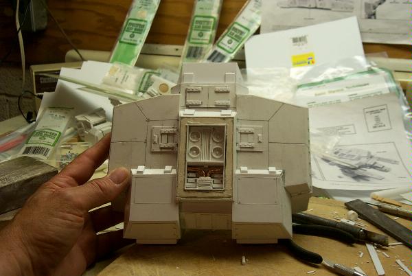 Awright so I ain't neat Blackadder
11292
Post by: Druidic
Try some mesh from a car body repair shop, for use with Fibre Glass, they can do some nice stuff.
Other option is B&Q, they sometimes does some nice decorative brass stuff.
10339
Post by: tallmantim
I have both nylon and aluminium fly wire/screening that would I think work well for what you want. Both available for nearly nicks at a hardware store.
You can see some of the nylon one on the picture below (a nurgling base my 9 YO daughter made).
The mesh one is about the same gauge but has individual weaved strands and holds shape when bent etc.
6568
Post by: Azmodai
Well your amazing with details! Those fans blow me away (pardon the pun...)
Keep it up, it's inspireing..
Azmo
6825
Post by: The_Blackadder
While I was installing the renforcement plates on the neck cowl I found I had a problem with the right side of the carapace where it joined the hull. Seems the angle was wrong and the more detail I added the more apparent it became. So I hacked the offending desecration off and rebuilt that section. Now you know why it's taking me forever to make any progress on this beastie.
One step forward and two steps back,
Blackadder
Automatically Appended Next Post: Thanks for all the help but I think I'll just bite the bullet and go for the gold er I mean brass.
http://www.hobbymasters.com/index.asp?PageAction=VIEWPROD&ProdID=4092
EB
9505
Post by: CaptainRavenclaw
Its really taken shape though. Keep slogging away.
6825
Post by: The_Blackadder
Hard to believe a week went by with so little to show for it. Pigment aficionadoes will be happy to note that I have begun painting by applying a coat of grey primer to the engine compartment. The head is coming along very well after I bit the bullet and with a good deal of trepidation drilled recesses for the "headlights, parking lights and directional signals" for want of better terms.
The hood and cheek vents look about done and the edging for the head armor will be installed tomorrow.
For those interested, thanks for the support.
Blackadder
3
9505
Post by: CaptainRavenclaw
That looks fantastic! I love the squares on the cheeks, are they an addition? Overall it'll be fantastic. Great work
6825
Post by: The_Blackadder
s.j.mccartney wrote:That looks fantastic! I love the squares on the cheeks, are they an addition? Overall it'll be fantastic. Great work
Thanks, the squares (vents? whatever) see below are on the original production Warhound. They will be embellished with the obligatory skulls etc as will 50% if the flat surfaces on this model.
More detailing to come,
Blackadder
1
6568
Post by: Azmodai
Your attention to details have already made me add more to my Warhound, and keep getting this feeling compelling me to do a bit more...
Made a new weapon for my Warhound , also... Needed a "destroyer" weapon to handle Red Skulls Stompa.
Positively love your plasticard Warhound!
Azmo
6825
Post by: The_Blackadder
Azmodai wrote:Your attention to details have already made me add more to my Warhound, and keep getting this feeling compelling me to do a bit more...
Made a new weapon for my Warhound , also... Needed a "destroyer" weapon to handle Red Skulls Stompa.
Positively love your plasticard Warhound!
Azmo
GEEZ! WEAPONS! I FORGOT ABOUT THOSE. Why doesn't Baldrick tell me these things. Thanks for reminding me, The complacent Blackadder
13640
Post by: Ranger4x4
Hey, I was at my local GW Battle Bunker, and I was looking around through the display case and I saw the Emperor class Titan stated earlier in this thread!
4003
Post by: Nurglitch
So far, so good. Do you need a good shouting out to conquer the tedium?
/Wellington
6825
Post by: The_Blackadder
Tell me about tedium!!!
I started installing the umpty ump rivets I lost count after 300. I'm using 0.020, 0.030, 0.040, 0.050. 0.060 dia styrene rods shaved 0.20mm thick, and half inch straight pins.
Blackadder's mixing his units of measurements as usual; how does he manage to keep it straight???
5
11457
Post by: Werdes
Wow it's looking awesome!
4670
Post by: Wehrkind
Holy crap... this is literally getting me twitchy with anticipation of my warhound getting made. I keep looking at all the flat surfaces and thinking "The murals! THINK OF THE MURALS!"
This is simply amazing, well done thus far!
Also, those nurglings are great. I might have to make some for my wife.
6825
Post by: The_Blackadder
It's rather difficult to present this without seeming to brag but I am fair bursting with pride over the outcome of the cockpit/head.
since I've completed most of the detail on the head I did a little 'Photoshopping' (Actually I use Photo Impact Pro #10 which I think is a better program than Photoshop.)
I still have the armor on the top of the head to do and the windows and windowframing replete with rivets need to be added after painting.
So I copied and pasted one of my images of a real Warhound head onto my recent image. I was greatly pleased and surprised how well it came out and would like to share it with all of you who have been so instrumental in keeping me on target in finishing this thing.
EB
1
15873
Post by: person person
It looks even more detailed than the forgeworld one!!!!!!! 
14869
Post by: Wrexasaur
I think yours looks a bit better than the standard one. The proportions and detail look much more realistic on yours.
Good job
9505
Post by: CaptainRavenclaw
You are da winner
6825
Post by: The_Blackadder
s.j.mccartney wrote:You are da winner
Thanks, but I haven't heard from my old pal and benefactor Jabba lately. I hope nothing's amiss.
I've installed dozens of rivets and am still finding more. How many are too many especially since they all have to be filed shorter after the glue dries. I'm still working on my first bottle of Tamiya Extra Thin Cement and it seems to be losing it's potency. does the stuff weaken if the top is not tightened after use as I am wont to do?
Anywho here's today's work and the start of the mega bolter. There's probably a better way to make this but I can't have too much weight up front.
Blackadder
1
11457
Post by: Werdes
Yea Rivets is the worst part
Keep going!
12393
Post by: BEASTSOFWAR
possibly the glues loosing some of the chemicals through evaporation, Just assuming because its thin it needs a lot of solvent to keep it that way.
Anyway this is a fantastic peice of work!
BoW- John
6825
Post by: The_Blackadder
BEASTSOFWAR wrote:possibly the glues loosing some of the chemicals through evaporation, Just assuming because its thin it needs a lot of solvent to keep it that way.
Anyway this is a fantastic peice of work!
BoW- John
Thanks Yes although there is no perceptible thickening of the liquid it doesn't seem to penetrate through capillary action as deeply as before. I had to put some clear glass marbles in the jar to deepen the liquid level for the brush to reach. Guess I should buy some more. Blackadder
6825
Post by: The_Blackadder
Werdes wrote:Yea Rivets is the worst part
Keep going!
Oh I'm going, yesterday evening in spite of a liberal imbibing of frozen Margaritas I managed to apply the first coat of primer to the head and manufacture the Void Shield Projector bases and the bases for the reactor exhausts.
As the rabbi said "It won't be long now",
Blackadder
5
967
Post by: slann
MMMMM margaritas are good , frozen is even better . Anyway titan looks freggin awsome you may have inspired me to try my hand at one of these when my guard are finished .
6825
Post by: The_Blackadder
slann wrote:MMMMM margaritas are good , frozen is even better . Anyway titan looks freggin awsome you may have inspired me to try my hand at one of these when my guard are finished .
Any help you need with material, measurements, etc don't hesitate to ask. I received a lot of help from this forum and would like to recipricate. I took some better pictures today without benefit of Margaritas....... Yet, Blackadder
5
7416
Post by: jabbakahut
The_Blackadder wrote:...I haven't heard from my old pal and benefactor Jabba lately.
Out of town camping on the Guadeloupe river in Texas. As always your work clearly rivals that of the original. I'm sure there is no need for me to point out any noticeable differences (as I'm aware that they probably all stick out to you). On the head, the windows on yours are a bit bigger and the snout a bit shorter, the angle of the rear structure/vents(?) seems like it might be a bit off. I only bring those up because I think the tighter windows and longer nose look a little better. Your rivets look much better than on the original. I'm not sure if you can tell in the photos-but the FW model rivets are rather small, more than a couple of mine didn't mold right. I should have just shaved them and made clean looking ones like yours. I really like the rivets work man. Some of the best work so far, will sadly go unnoticed. The underside of the head is incredible and the back of the carapace is impeccable. Also the details on the right and left of the snout just forward and under the armor look phenomenal as well. Are you doing any interior work?
6825
Post by: The_Blackadder
jabbakahut wrote:Out of town camping on the Guadeloupe river in Texas. As always your work clearly rivals that of the original. I'm sure there is no need for me to point out any noticeable differences (as I'm aware that they probably all stick out to you).
Noticeable differences Indeed!!! Sir you take great liberties. Yes I am fully aware of the discrepancies many of which are intentional but alas a few that are not. I appreciate your candor. Surprisingly no one has picked up on the most obvious difference in that the carapace on mine does not taper toward the front as in the original. In most of the scratch build plans I've seen this angle is much too extreme. I decided to make my prototype parallel with the engine vent compartment and pare the angle in to what I felt was the proper angle. Ultimately I decided parallel looked best. jabbakahut wrote:On the head, the windows on yours are a bit bigger and the snout a bit shorter, the angle of the rear structure/vents(?) seems like it might be a bit off. I only bring those up because I think the tighter windows and longer nose look a little better.
My windows are only the interior frames as yet. I've still got to install the clear styrene and exterior frames and the roof overhang so that will be easily rectified. Interesting that you think the snout is too short. My original head had a longer snout by approx 3/16 inch but I though it looked too long so when I rebuilt it I made the muzzle shorter. I thought it conveyed a greater impression of strength; a 'pug'nacious demeanor if you will. The rear vents in what would be the ear area gave me a good deal of trouble and I rebuilt them three times. Having only perspective images to go by I gave it my best shot. They fall short of the ideal but will be hidden from all but the most scrutinous inspection by the hood. jabbakahut wrote:Your rivets look much better than on the original. I'm not sure if you can tell in the photos-but the FW model rivets are rather small, more than a couple of mine didn't mold right. I should have just shaved them and made clean looking ones like yours. I really like the rivets work man.
Until I saw your manual I was not even aware of the rivets in the head armor. They are so small that the paint obscures them in most of the images I had previously. I made mine larger but still they are undersized for the size and the weigh that shielding must have. I whilst installing these umpty-ump rivets continually reflected on how woefully inadequate these rivet and bolt patterns are for a vehicle of this size. Take a look at the trailer on the next Semi you incounter on the road. and notice the rivet pattern for just afixing thin sheet metal on a non-combat vehicle. Having worked on jet aircraft and inspected the steel hulls of old passenger liners; I can tell you that fist sized rivets 12 to 24 inches apart will not do the job. I put them in for the same reason the original artist/designer did. To break up large empty expanses of slab siding. jabbakahut wrote:Some of the best work so far, will sadly go unnoticed. The underside of the head is incredible and the back of the carapace is impeccable. Also the details on the right and left of the snout just forward and under the armor look phenomenal as well.
The underside of the head which I am very happy with was surprisingly easy to do. Aside from the pictures you so graciously provided I have never seen any images of this highly detailed area. I really prefer the 'moulded in' Void Shield Generator housings to the FW model. The gap between the engine vent housing and the generator housing always gave me the impression of a Model 'T' Ford technology. If I am ever fortuanate enough to own and build an original FW Warhound I will change this area to copy my design. Another thing I cannot bring myself to do is cut the tabs into the skin on the top of the carapaces. I have tried sketching them in but they always detract from the overall effect to my eye. I have decided to leave them out. jabbakahut wrote:Are you doing any interior work?
Aside from the engine vent compartment in which I stole your colour scheme if you don't mind and installing busts of drivers in the cab there will be no other interior appointments. I toyed with the idea of a complete interior but felt the material was not up to the challenge as far as strength. Thanks for the critique, Blackadder More rivet detail It took me 3 hours to install the 196 rivets on the caps for the leg joints not to mention the interior of the hip swivel drums. Talk about tedious. I still have to install the rosettes on the caps but decided to take a break and take some pictures. In all the caps took 3 days to manufacture and I don't relish repeating this part of the project but I still have the toes to do IIIEEEE! EB
2
7899
Post by: The Dreadnote
Dude, you have a problem. An awesome problem.
6825
Post by: The_Blackadder
The Dreadnote wrote:Dude, you have a problem. An awesome problem.
Are you speakingas far as; mentally, manufacturing-wise or both? EB
7899
Post by: The Dreadnote
In that you're the kind of person who will spend three days installing rivets, where your average person would say "nah, too much hard work".
7416
Post by: jabbakahut
The_Blackadder wrote:Surprisingly no one has picked up on the most obvious difference in that the carapace on mine does not taper toward the front as in the original. In most of the scratch build plans I've seen this angle is much too extreme. I decided to make my prototype parallel with the engine vent compartment and pare the angle in to what I felt was the proper angle. Ultimately I decided parallel looked best.
I had to go get mine off the shelf to verify, I doubt in anybody would notice that. I wasn't even aware of it on my own model. It is a very subtle angle, I see the problems in getting that right. I think the parallel works just fine.
15873
Post by: person person
Didn't notice...
6825
Post by: The_Blackadder
I didn't imagine it and I'm glad it's not noticable on the standard model. I've seen a few scratchbuilts on this pattern and it make the overall effect make it look weak. IMHO I hastly add. EB Automatically Appended Next Post: The Dreadnote wrote:In that you're the kind of person who will spend three days installing rivets, where your average person would say "nah, too much hard work".
I.E. Manic Obsessive but "hours" on these particular rivets.
Blackadder
6825
Post by: The_Blackadder
Okay folks the next time you see this hull for better or worse it will have a coat of primer in it. As soon as I get these pictures uploaded I'm gonna paint this sucker. I did a crash program marathon to get it ready for paint this weekend installing something like 200+ more rivets and the rest carapace underside detail. I replaced the six link coupler tubes with styrene tubes in between the generators.
Question of probablilities for you math and physics wiz's out there:
I've studied a little quantum physics and the Heisenberg uncertainty principle but I'm at a loss to explain why when you install a rivet approximately 0.030inches in diameter and 0.015inches thick it invariably stands on edge instead of lying on the flat disc surface. I've even tried to stand it on edge (even though I really want it to lie flat just to confuse the gods of the laws of probablity) and the damned things still stand on edge. It's like flipping a coin a hundred times and every time it stands on edge.
Now here's the real kicker; on a piece of scrap I deliberately tried to stand these tiny disks on edge and they lie flat every time.
I think my basement is haunted by Schrodinger's cat,
Blackadder
13
4003
Post by: Nurglitch
The_Blackadder:
I don't think you're dealing with quantum mechanics, unless you're a really crazy rivetter. I think you're dealing with good old surface tension, dissolving polymers, and the relative static charges of the plastic pieces. I imagine, and this is a bit of a just-so story, that the rivets you've cut out have microscopically rough edges, where there loose-ends of styrene polymers that catch much more easily on the unraveling polymers that are being dissolved by the cement you're applying. And the charge orients the rivets edge on. So, not really rivets, but molecular bonding studs!
6825
Post by: The_Blackadder
Nurglitch wrote:The_Blackadder:
I don't think you're dealing with quantum mechanics, unless you're a really crazy rivetter. I think you're dealing with good old surface tension, dissolving polymers, and the relative static charges of the plastic pieces. I imagine, and this is a bit of a just-so story, that the rivets you've cut out have microscopically rough edges, where there loose-ends of styrene polymers that catch much more easily on the unraveling polymers that are being dissolved by the cement you're applying. And the charge orients the rivets edge on. So, not really rivets, but molecular bonding studs!
So you're saying that the rivets are so small that static electricity is causing them to stand on edge???
Thanks,
EB
4003
Post by: Nurglitch
Not exactly. I'm suggesting that maybe the studs are so small that a combination of static electricity, loose polymers, and surface tension made them stand on edge.
8551
Post by: captain.gordino
This is such a nice scratchbuild. Pure win.
9395
Post by: CMDante
Wow.
Here's how great a job I think your doing here, in those last few sets of pics I actually thought you had replaced the head you had been scratch building (not that I thought you needed to) with the head of a FW warhound, turns out you'd just primed it grey!
Really fantastic scratch build. Something I could only ever dream of as I completely lack the patience required to cut plasticard accurately in such volumes.
Bravo, I look forward to the finished beast.
Cheers,
Dante
6825
Post by: The_Blackadder
CMDante wrote:Wow.
Here's how great a job I think your doing here, in those last few sets of pics I actually thought you had replaced the head you had been scratch building (not that I thought you needed to) with the head of a FW warhound, turns out you'd just primed it grey!
Really fantastic scratch build. Something I could only ever dream of as I completely lack the patience required to cut plasticard accurately in such volumes.
Bravo, I look forward to the finished beast.
Cheers,
Dante
Thanks but don't sell yourself short. Cutting plasticard needn't be a chore. Rough cut the card slightly oversize and glue in place with thin liquid cement. After it dries dress the intersecting panels with a fine file and voila; a perfect edge and or seam. THe only real pain in the a-- (and only because there are so many of them) are the rivets. EB
15100
Post by: SgtPunishment
I've had to tie my jaw to my head, it refuses to stay closed, it's seriously jaw dropping amazing how much detail and love you've put into this project. I wish the best
9504
Post by: sonofruss
You missed a rivet it section 19-3 it will fall apart.
6825
Post by: The_Blackadder
sonofruss wrote:You missed a rivet it section 19-3 it will fall apart.
Got it. Thanks,
Blackadder
15873
Post by: person person
captain.gordino wrote:This is such a nice scratchbuild. Pure win.
AGREED!!!
13159
Post by: inquisitor_lord_slade
Unbelievably awesome. I can't believe that ANYONE could scratchbuild that. Pure genius man. Keep up the great work.
6825
Post by: The_Blackadder
I appreciate the kind words and I hope this next set of pictures justify your accolades. One thing for certain; I won't be painting the this model all primer grey as I did on all my tank models. I just lacks panache so I just might go with one of the FW paint jobs after all.
I have one in mind but I would take a few suggestions gladly. The painting of this beast is a one shot affair and I want to get it right.
As of now it's as plain as a mud fence,
Blackadder
7
8266
Post by: Wolf
Holy titan batman ! That is exceptionally good, it really doies look like a forgeworld model, it's that accurate !
5832
Post by: jamessearle0
*whistles* mhm, mucho detail there mate needs more finishing
6825
Post by: The_Blackadder
Wolf wrote:Holy titan batman ! That is exceptionally good, it really does look like a forgeworld model, it's that accurate !
Ah yes the renown British mastery of understatement and sophistication as demonstrated by your avatar and who pray tell might that individual be mugging for the camera???
jamessearle0 wrote:*whistles* mhm, mucho detail there mate needs more finishing
Noted, I had thought of putting wheels on it and offering it as a bilateral amputee but yours is a viable option as well
Thanks for the replies and forgive my jocular responses but I couldn't resist.
The incorrigible Blackadder
6825
Post by: The_Blackadder
Not much to report this weekend; I've been rather busy. I managed to put the detail on one leg: rivets, joint caps and braces on the lower leg around the hydraulics. It's amazing how much thought went into the design of this model. You would think there were actually a working Warhound that the designer took his plans from. Virtually everything makes sense from a technical point of view. From a practical well thats another story.
I also rebuilt three of the eight toes. The poor things took a real beating these past few months and were just too flimsy to stand the gaff of time so I re-designed them stronger and more flexible.
Blackadder
4
7416
Post by: jabbakahut
The_Blackadder wrote:It's amazing how much thought went into the design of this model. You would think there were actually a working Warhound that the designer took his plans from. Virtually everything makes sense from a technical point of view. From a practical well thats another story.
I know, right? I began to wonder if you mod this thing into a r/c robot.
6825
Post by: The_Blackadder
I may be mad but I'm not crazy. Making this thing into a functioning robot would be next to impossible. Even Nasa baulked at a bipedal robot as inherently unstable.
Nice to hear from you none the less,
Blackadder
7416
Post by: jabbakahut
The_Blackadder wrote:I may be mad but I'm not crazy. Making this thing into a functioning robot would be next to impossible. Even Nasa baulked at a bipedal robot as inherently unstable.
Nice to hear from you none the less,
Blackadder
I wouldn't try it, but have you seen those fighting Japanese robots? It it not unheard of.
4216
Post by: Darknight
You just need a very small person, or perhaps a group of trained hamsters, to man it.
13483
Post by: Dakka_Dok
Astro-dwarfs, using ancient rune lore to power their mighty machines. 
4003
Post by: Nurglitch
I always figured Titans were replete with suspensors. AFter all, isn't the suspensor effect just the secondary effect of Holtzmann generators? They need Plasma reactors to hold themselves up, as well as power their shields, weapons, and so on. It's not that Mars can't build giant robots, but building robots that are actually stable and efficient requires resources that are running out in the Imperium. Grav-plates are required for anti-gravity vehicles such as Land Speeders and starship grav-plating.
7416
Post by: jabbakahut
Nurglitch wrote:I always figured Titans were replete with suspensors. AFter all, isn't the suspensor effect just the secondary effect of Holtzmann generators? They need Plasma reactors to hold themselves up, as well as power their shields, weapons, and so on. It's not that Mars can't build giant robots, but building robots that are actually stable and efficient requires resources that are running out in the Imperium. Grav-plates are required for anti-gravity vehicles such as Land Speeders and starship grav-plating.
Wow, that is some deep cannon gak. Have you read everything? I thought I was well read, good answer.
6825
Post by: The_Blackadder
Nurglitch wrote:I always figured Titans were replete with suspensors. AFter all, isn't the suspensor effect just the secondary effect of Holtzmann generators? They need Plasma reactors to hold themselves up, as well as power their shields, weapons, and so on. It's not that Mars can't build giant robots, but building robots that are actually stable and efficient requires resources that are running out in the Imperium. Grav-plates are required for anti-gravity vehicles such as Land Speeders and starship grav-plating.
Interesting answer; I always wondered what actually powered these things but what really piques my concern is: How do the hydraulics work without hoses????
Inquiring minds want to know,
Blackadder
10339
Post by: tallmantim
Nurglitch wrote:I always figured Titans were replete with suspensors. AFter all, isn't the suspensor effect just the secondary effect of Holtzmann generators? They need Plasma reactors to hold themselves up, as well as power their shields, weapons, and so on. It's not that Mars can't build giant robots, but building robots that are actually stable and efficient requires resources that are running out in the Imperium. Grav-plates are required for anti-gravity vehicles such as Land Speeders and starship grav-plating.
Holtzman is from Dune - the inventor of the Holtzman field that allowed the folding of space amongst other things.
The_Blackadder wrote:
Interesting answer; I always wondered what actually powered these things but what really piques my concern is: How do the hydraulics work without hoses????
Inquiring minds want to know,
Blackadder
Easy - they use their teleportation technology to teleport the hydraulic fluid in and out!
Makes maintenance and ruggidity to attack better!
12212
Post by: Lord Kaesar II
Well, though impractical, you could put the release and intake inside the pistons. Also, though bipedal stuff is suggested to be unstable, we successfully stand after a year or so of work. Just wire some people into your remote controller and bam, you've got a feral warhound running loose on the tabletop
6825
Post by: The_Blackadder
tallmantim wrote:The_Blackadder wrote:
Interesting answer; I always wondered what actually powered these things but what really piques my concern is: How do the hydraulics work without hoses????
Inquiring minds want to know,
Blackadder
Easy - they use their teleportation technology to teleport the hydraulic fluid in and out!
I see; and they teleport the hydraulic pressure as well? Hmmm. (He quiried wryly.)
The problem there is suppose you transport a gallon of hydraulic fluild into a space that only has room for say for the sake of arguement a quart. (or for you backwards individuals that still use the metric system '4 liters into a 1 liter space'.) For an instant there is infinite pressure inside the hydraulic cylinder and the d--ned thing explodes. One might just as easily transport the jot of fluid into the enemy as save the need for guns etc n'est pas.
Blackadder
7416
Post by: jabbakahut
The_Blackadder wrote:Nurglitch wrote:I always figured Titans were replete with suspensors. AFter all, isn't the suspensor effect just the secondary effect of Holtzmann generators? They need Plasma reactors to hold themselves up, as well as power their shields, weapons, and so on. It's not that Mars can't build giant robots, but building robots that are actually stable and efficient requires resources that are running out in the Imperium. Grav-plates are required for anti-gravity vehicles such as Land Speeders and starship grav-plating.
Interesting answer; I always wondered what actually powered these things but what really piques my concern is: How do the hydraulics work without hoses????
Inquiring minds want to know,
Blackadder
Come on, it's the 41st century, the alleged hydraulic cylinders are actual servo operated. Instead of fluid under pressure being the force generator, the two half's of the piston act as a rotor and stator, the precision of complex movements can be seen in modern stepper motors for robotics. The energy consumption to operate these draws such a huge current that the bulk of the titan is dedicated to is fusion generators which provide the power needed to operator the 'servos'.
6825
Post by: The_Blackadder
jabbakahut wrote:The_Blackadder wrote:Nurglitch wrote:I always figured Titans were replete with suspensors. AFter all, isn't the suspensor effect just the secondary effect of Holtzmann generators? They need Plasma reactors to hold themselves up, as well as power their shields, weapons, and so on. It's not that Mars can't build giant robots, but building robots that are actually stable and efficient requires resources that are running out in the Imperium. Grav-plates are required for anti-gravity vehicles such as Land Speeders and starship grav-plating.
Interesting answer; I always wondered what actually powered these things but what really piques my concern is: How do the hydraulics work without hoses????
Inquiring minds want to know,
Blackadder
Come on, it's the 41st century, the alleged hydraulic cylinders are actual servo operated. Instead of fluid under pressure being the force generator, the two half's of the piston act as a rotor and stator, the precision of complex movements can be seen in modern stepper motors for robotics. The energy consumption to operate these draws such a huge current that the bulk of the titan is dedicated to is fusion generators which provide the power needed to operator the 'servos'.
In that case there would be required equally large electrical cables to run the servos which should be visable unless the electric power is transported as well?
EB
11330
Post by: Gundam-Mecha
Fantastic work Blackadder!
Sorry I didn't get to send you those photos of the Warhound legs, I was away on holiday for ages! I guess you wont need the reference photos anymore?
As to the hydros and pistons why not model on some cabling? It would be a nice realy world touch. I'm going to add washer hoses and electrical cabling to my T-55 to detail it up. I think little things like that really add to a large kit.
4216
Post by: Darknight
I have come across the problem of where the cables and lines are on a "mecha" model I am building. This model actually has very few visible servos and hydralic cylinders. However, despite what Warhammer 40,000 has taught us, the idea that a sophisticated engine of war would have exposed cables and lines is slightly foolish. People do not expose "worky-stuff" unless they have to.
So, I would argue the lines, cables, hoses etc. are internal, or at least hidden under the armor. For a historical diorama like Gundam-Mecha's we must be informed by actuality, but for a more fantasy piece (such as my "mecha" or this awesome Titan thing) we should decide what is suitable.
My model has a "clean" look which cables etc. would spoil. But I think a 40K Warhound would look good with some more exposed "worky bits".
6825
Post by: The_Blackadder
Not to flog an already dead horse but the cockpit power and telemetry cables are in full view and no doubt a tempting target for those who wish to bring down one of these brutes. Now not being up on what a void shield is capable of shielding against (I'm just into it for the model building not playing the game thats my son's department.) Can a well place projectile penetrate the shield; i.e. can a Warhound be brought down by a bazooka round?
Well you could ask your son, Blackadder
12212
Post by: Lord Kaesar II
Well, void shields don't work so much in that they mostly deflect something, but rather just open a hole in the materium where the shot is and shoot it into the warp, thereby missing the titan. Basically, a missile at long range can't get a titan with void shields still up, but a close by one can do some damage, but only just barely.
4003
Post by: Nurglitch
I always imagined that a void shield acted as a zero-point energy converter, except that instead of producing energy, it converted it and stored it in capacitators, which would shut down as they became charged. Hence a Titan could absorb a certain amount of energy because its Void Shield Generators shut down and had to be drained.
Read "The Mote in God's Eye" for a great sci-fi analog to the Void Shield, the Langston Field.
6825
Post by: The_Blackadder
It seems to me that a lone Titan without ground support would be vulnerable to an evilly disposed individual wielding an ax then or cannot a person penetrate a void shield either?
A couple of chops and there go the ankle hydraulics.
Blackadder
15873
Post by: person person
 what if all the "exposed wires etc." didn't do anything at all! So the enemy wastes time thinking, "That looks important. BAM! Nothing happened. I'll shoot that other work bit. BAM! Nothing happened."
4003
Post by: Nurglitch
Or consider the difficulties and dangers of closing with a moving piece of heavy machinery. Remember that force is mass times acceleration, so even a slowly accelerating Titan toe is going to hit really hard if your timing is slightly off or your footing isn't sure.
7899
Post by: The Dreadnote
The_Blackadder wrote:It seems to me that a lone Titan without ground support would be vulnerable to an evilly disposed individual wielding an ax then or cannot a person penetrate a void shield either?
A couple of chops and there go the ankle hydraulics.
Blackadder
I've not personally seen any evidence that points one way or the other. There's the single issue of the Titan graphic novel in my local library, but I don't recall if the voids were up during the boarding scene featured. Down, I think.
6568
Post by: Azmodai
The Dreadnote wrote:The_Blackadder wrote:It seems to me that a lone Titan without ground support would be vulnerable to an evilly disposed individual wielding an ax then or cannot a person penetrate a void shield either?
A couple of chops and there go the ankle hydraulics.
Blackadder
I've not personally seen any evidence that points one way or the other. There's the single issue of the Titan graphic novel in my local library, but I don't recall if the voids were up during the boarding scene featured. Down, I think.
In Warhammer monthly issue 11 and 12 there were a Ravenwing story. They took out a stompa by going in under it, an throwing in some explosives. In order to get through the shields of the stompa they had to stop and let the shield pass over them, the brother who tried to drive through it met a hard barrier that crushed his bike...
Though not Void shields, the power shields of the Orks is comperable in function....
Azmo
4216
Post by: Darknight
Heavy machinery IS vulnerable to infantry, because infantry can carry devastating weapons and move very fast and are very small. Also, heavy machinery generally does see what is going on very well - look at the small vision slits etc. on tanks.
This is why the Armored Company rules (originally at least) had rules tanks could not come within a certain distance of cover without infantry support.
Unless a Titan has sensors which send huge amounts of information to the crew (and it can respond fast enough) or has auto-anti-infantry systems (such as auto-targetting bolters or autoguns firing at anything which scurries around its feet) it is going to need infantry support.
I always envisaged Titans were accompanied to battle by squads of heavy infantry, scurrying around the feet, sometimes hitching a lift on the feet, constantly communicating with the Titan crew. Perhaps a few sentinels. They would be highly trained to not get stepped on, of course.
6825
Post by: The_Blackadder
Nurglitch wrote:Or consider the difficulties and dangers of closing with a moving piece of heavy machinery. Remember that force is mass times acceleration, so even a slowly accelerating Titan toe is going to hit really hard if your timing is slightly off or your footing isn't sure.
Most mechanized vehicles are vulnerable from the rear and that is where to approach them from. Granted the Warhound is capable of great speed but probably doesn't employ that capacity all the time as it would outrun its ground support. The Warhound doesn't seem to have any secondary weaponry. Other than the void shields what defenses does it have against determined ground personnel?
Tanks at least have a turret that can cover 360° with secondary machine gun fire.
Newton not withstanding,
Blackadder
967
Post by: slann
Iam sure there ae hatches where the crew inside can open and lend some small arms fie support .
18138
Post by: titasah64
Great work I wish I had half the modeling talent and patients you had.
9230
Post by: Trasvi
The_Blackadder wrote:(or for you backwards individuals that still use the metric system '4 liters into a 1 liter space'.)
Lol are you serious?
In other news absolutely FANTASTIC model. Perfect in every way. Have you decided what color scheme?
6825
Post by: The_Blackadder
Trasvi wrote:The_Blackadder wrote:(or for you backwards individuals that still use the metric system '4 liters into a 1 liter space'.)
Lol are you serious?
No of course not still there are a few areas where the American Standard of measure archaic as it is is superior to the metric system such as linear measurments for model building for unless I am wrong there is no gradient less than a millimeter on the 'standard metric scale' and the ' AS scale' I use gives me measure units of 1/64 inch. (I also have one graded in 1/128 but I'm not a fanatic.) There are approximately 3mm to an 1/8 inch whereas there are 8/64ths to 1/8 inch. Unless there is a metric ruler that can split the millimeter into quarters I shall continue to use the AS scale. Perhaps that is why my fine detail work may seem so "unbelievable" (If I may be so unabashed to quote the general run of these replies); You guys gotta get better rulers. Blackadder
9230
Post by: Trasvi
Of course there are gradients less than millimeters. Micrometers, Nanometers etc. Thats the whole point of metric The ruler I use for modelling goes down to 0.25mm, most rulers only do 1mm (but then again most imperial rulers only go to 1/32")
Perhaps extremely fine detail work with rulers is the one situation where imperial rulers can be better than metric, but I wouldn't go so far as to call the Metric system backwards. Although, maybe I'm biased, coming at this from a physics/engineering POV.
Anyway, look forward to seeing more updates Keep up the great work.
6825
Post by: The_Blackadder
Trasvi wrote:Of course there are gradients less than millimeters. Micrometers, Nanometers etc. Thats the whole point of metric The ruler I use for modelling goes down to 0.25mm, most rulers only do 1mm (but then again most imperial rulers only go to 1/32") Perhaps extremely fine detail work with rulers is the one situation where imperial rulers can be better than metric, but I wouldn't go so far as to call the Metric system backwards. Although, maybe I'm biased, coming at this from a physics/engineering POV. Anyway, look forward to seeing more updates Keep up the great work.
I'm fully aware of the smaller divisions of the mm including 'pico', 'femto', 'atto' and ångström (non SI) units all the way down to 'yocto' (i.e. one septillionth of a meter). I didn't call the metric system backwards except to make a joke earlier but to have a scale splitting a mm into quarters would be great. (incongruous as that seems to me as the "whole point" of the metric system is to have all units divisible by 10. The very fact that the concession is made reinforces the argument). Now if the meter could be broken into thirds it would be more convienient for say carpentry. The incorrigible Blackadder
6825
Post by: The_Blackadder
I haven't forgotten about this thread. I'm just going through the interminable process of rebuilding the toes and detailing them. Although they are a lot leaner than before they are much stronger and more to scale; especially the joints. The row of cylinders in front are the joint caps left to do in various stages of completion FYI. Twenty eight caps in all to do =280 rivets just for the caps alone. Whew!
Blackadder
2
4746
Post by: Flachzange
Psh, like we wanne hear you complain. Rivet faster darn it!!
Epic build really!
6825
Post by: The_Blackadder
Flachzange wrote:Psh, like we wanne hear you complain. Rivet faster darn it!!
Jawohl mein Fuhrer! EB Where is "Monasteria?"
4216
Post by: Darknight
That is a truly insane level of dedication to detail, and I salute you for it. This model is going to be absolutely fantastic when it is complete.
Do you have any idea how many hours you have spent on this model, or is such a calculus the key to the carefully-locked portal to an unending realm of madness consisting of a cathedral made entirely from the flayed skin of the damned and inhabited by the wailing of a trillion crystaline bees, where the light only casts shadows and does not illuminate?
I ask because I would suspect the original FW model took at least as long to sculpt, and such a figure might support the high profit margins (vs. raw material costs) of the FW stuff.
6825
Post by: The_Blackadder
Darknight wrote:That is a truly insane level of dedication to detail, and I salute you for it. This model is going to be absolutely fantastic when it is complete.
Do you have any idea how many hours you have spent on this model,
It's really hard to estimate how much time as I made a lot of failed starts. Initially I started this model early in 2008 but my job interfered with doing anything but the hull and carapace. I put the whole thing on back burner while I started a new career and resolved 01/01/09 to make an effort to resume building. I piddled around for two months trying to figure out how to make the toes and joints moveable and really started in ernest 03/01/09. I work in spurts doing nothing for days on end and the putting in 6 to 8 hours at a stretch in the wee hours of the morning ( I get up at 3AM everyday and officially start work at 9AM.) I conservatively estimate I average an hour a day so 150 hours would probably be about right. Considering my payrate this thing is costing tens of thousands of dollars so I really am not ahead of the game not buying one outright but wheres the fun in that.
or is such a calculus the key to the carefully-locked portal to an unending realm of madness consisting of a cathedral made entirely from the flayed skin of the damned and inhabited by the wailing of a trillion crystaline bees, where the light only casts shadows and does not illuminate?
Not for anything would I interupt the mellifluous flow of the above statment.
I ask because I would suspect the original FW model took at least as long to sculpt, and such a figure might support the high profit margins (vs. raw material costs) of the FW stuff.
I rather think that the whole model wasn't sculpted but that the duplicate components where sculped and cast to save the tedium of repetition. It takes a psychotic level of masochism to make the same pieces over and over.
From one who knows,
THe Blackadder
6825
Post by: The_Blackadder
I couldn't find any decent figures except for some old Catachans and my Lucius Baneblade Arethusa
The toes are just placed in front of the foot pad so I have to hold the model.
If you look real close at the # 3 toe there is my first hydraulic cylinder in place. Sorry no macro lens on this camera.
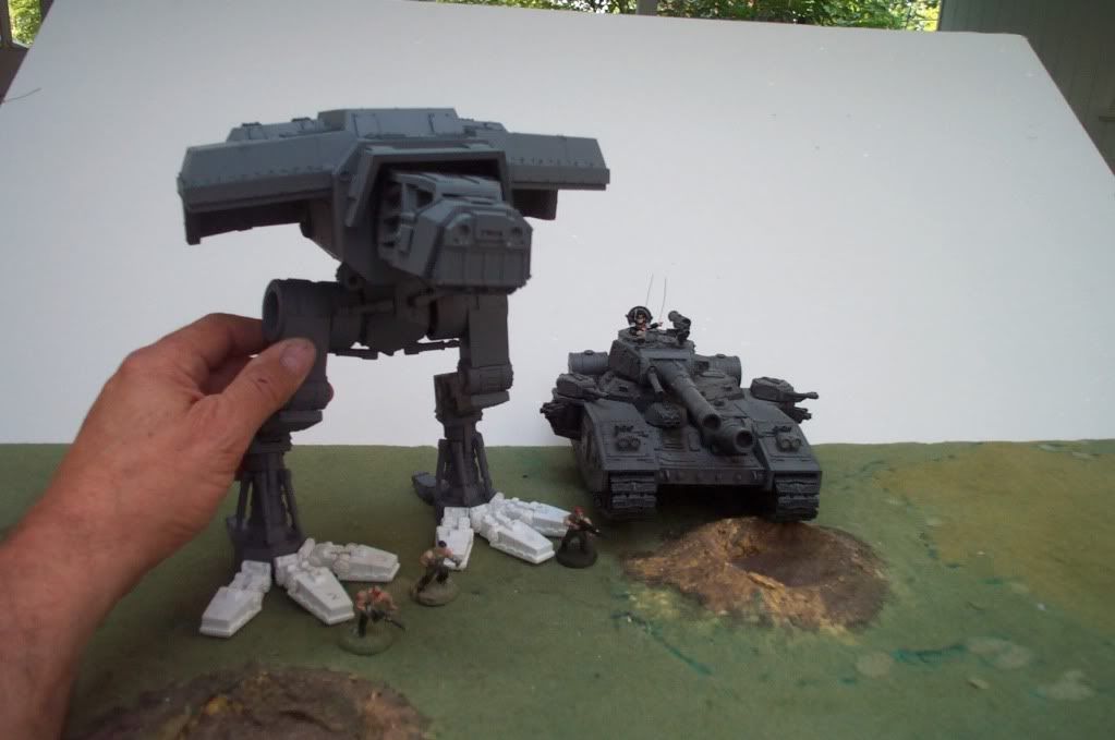
 EB
EB
15873
Post by: person person
WOW can't wait to see it finished.
7416
Post by: jabbakahut
I don't see armor plating on the thigh? Are you keeping those off with the shin armor for painting?
6825
Post by: The_Blackadder
jabbakahut wrote:I don't see armor plating on the thigh? Are you keeping those off with the shin armor for painting?
My order of priorities:
Toes have to be finished first because they are the hardest, most tedious and the damned thing can't stand without them.
Armor has still to be fabricated but unless it can stand on it's own there is not much point in attaching the armor.
design a clip to attach the armor for easy removing. (maybe magnets)
Finish building the armament.
Add weights to the rear of the generator housings for stability and balance.
Paint the detail.
Install top of head armor and windows/windshield to cockpit.
Vow never to become engrossed in another project of this magnitude.
I've learned my lesson,
EB 
4216
Post by: Darknight
You forgot the final step;
Break vow.
17463
Post by: SargesSquad
Looks fantastic. This is really coming together.
Can't wait to see it finished.
One (extra) final step:
Take thread and turn it into the biggest, most jaw-dropping tutorial on Dakka to date.
6825
Post by: The_Blackadder

The literally hundreds of components in the toes alone not counting the mistakes, redos, and redesigns. I wouldn't recommend this project for those who frustrate easily.

Each toe is fully articulated and as close to the scle of the original as the material will allow.

The #2 toe components exploded view

A very grainy image of the #3 toe forward hydrualics
The #3 toe in flat position

The #3 toe flexed not much of a range of motion for all that work!
The reason the Blackadder is certifiable
6
15636
Post by: Gavvin Quinn
Is there any chance that you will be publishing templates for your toes? Those are absolutely amazing. I want to get active again on my warhound, but I have been so busy. Every time I look at my modelling table, I see at least half a dozen unfinished projects beckoning.
6825
Post by: The_Blackadder
Gavvin Quinn wrote:Is there any chance that you will be publishing templates for your toes? Those are absolutely amazing. I want to get active again on my warhound, but I have been so busy. Every time I look at my modelling table, I see at least half a dozen unfinished projects beckoning.
Sorry to say I have no templates for the toes or any other part of the vehicle. All I have are hundreds of images I have gleaned from various sources on the internet. There is also the problem of copyright infringements. FW and GW take a dim view of people publishing the measurements of their products and rightly so. Also, I have no way of knowing how accurate my components are as far as size. My greatest fear is after I complete this model and show it off at some games meet someone shows up with a real Warhound and mine is ridiculously small or ungainly large and all this work will be for nought. At that point I 'll waggle it's toes at them. I'd be happy to coach you on any part of the construction but I've already been cautioned elsewhere on producing templates. After all we don't want this forum shut down do we?
Blackadder
7416
Post by: jabbakahut
The_Blackadder wrote:...I've already been cautioned elsewhere on producing templates.
By GW officially, or just some forum mods?
6825
Post by: The_Blackadder
Actually it was a forum policy because of complaints by GW for posted paper model templates. Have you been away for the summer? I took a week off from modeling after finding the forward toe cylinders as presented on the original model are too short to function properly on an actual moveable construction. I got so P.O.'ed I lost interest in the whole thing for a while. I really should do some drawings of these toes. They are the hardest part of the whole model especially if you want them moveable. The dual cylinders at the base of the toes are particlarly hard to manufactureas they are about 4.5mm long and I still haven't figured a way to mount the knuckle end of the piston. I might have to forgo that bit of articulation.
EB
1
9788
Post by: goffnob deffsmakka
Nice scratchbuilt you got there, I seriously can't wait to see it finished.
|
|